EasyManuals Logo
Home>Epson>Robotics>G20 Series

Epson G20 Series User Manual

Epson G20 Series
252 pages
To Next Page IconTo Next Page
To Previous Page IconTo Previous Page
Page #113 background imageLoading...
Page #113 background image
Maintenance 2. General Maintenance
G10 / G20 Rev.20 101
2.6 Layout of Maintenance Parts
G10-65*** manipulator of S/N: 1**** or later is different from other models in its
maintenance parts position.
For the detail, refer to Setup & Operation 2.6.4 G10-65***: For S/N: 1**** or later.
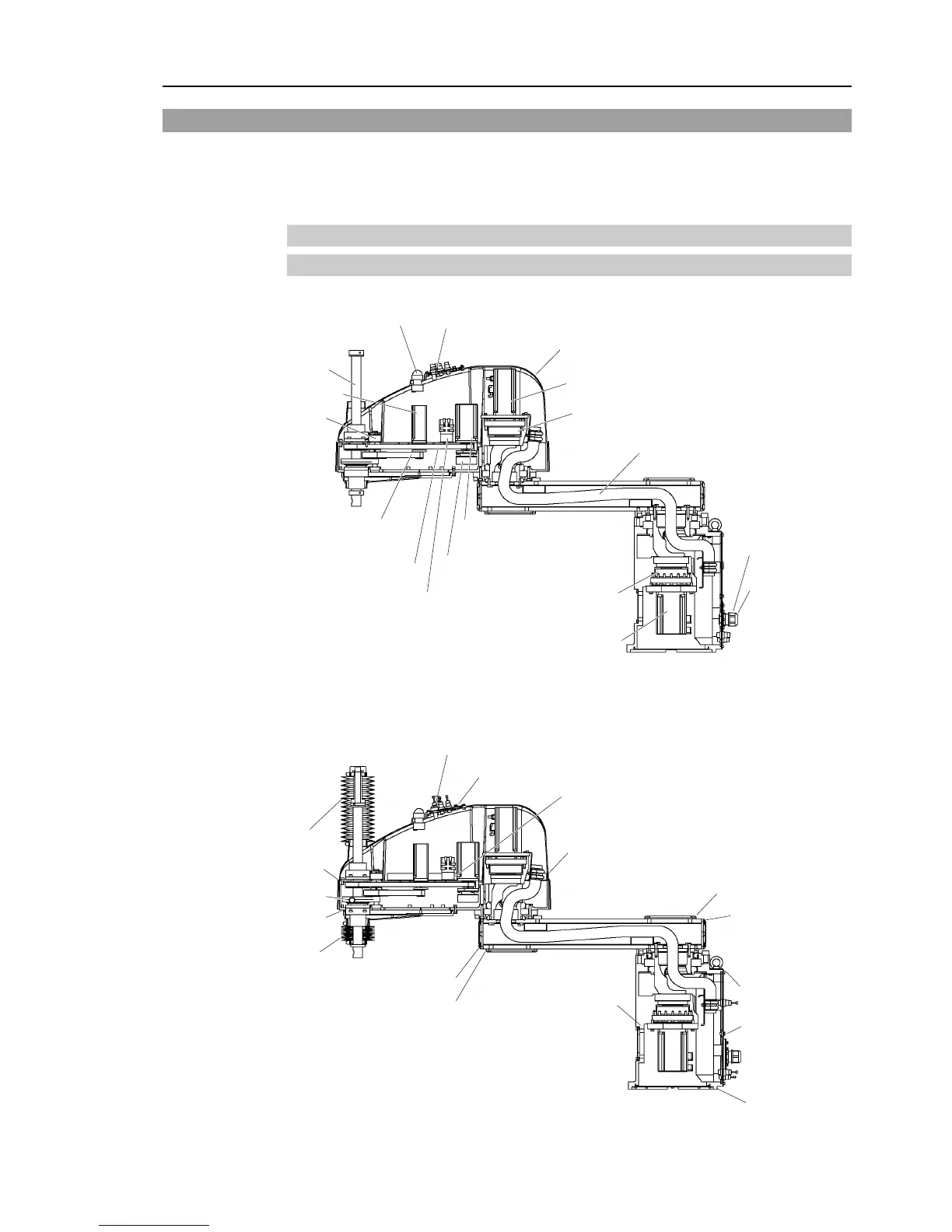
2.6.1 Table Top Mounting type
G10
G10-***S : Standard-model
Joint #3 motor
Lithium battery and Battery board
Joint #1 motor
Joint #2 reduction gear unit
Joint #1
reduction gear unit
Brake release switch
Ball screw spline unit
Joint #4 motor
Cable unit
Z belt
U belt
Joint #2 motor
Joint #4 brake
Arm cover
Joint #3 brake
(Figure: G10-851S)
LED lamp
Power cable
Signal cable
G10-***C : Cleanroom-model
G10-***D, P : Protected-model (D: With bellows option)
Bellows (C, D, P)
Brake release switch (for D, P)
Bellows (C, D, P)
Gasket (D
, P)
Gasket (P)
Gasket (D, P)
Gasket (D, P)
Gasket (D, P)
Gasket (D, P)
Gasket (D, P)
Gasket (D, P)
Gasket (D, P)
Gasket (D, P)
Gasket (P)
Gasket (C
, D, P)
(Figure: G10-851P)
O-ring (D
, P)
Gasket (P)

Table of Contents

Questions and Answers:

Question and Answer IconNeed help?

Do you have a question about the Epson G20 Series and is the answer not in the manual?

Epson G20 Series Specifications

General IconGeneral
BrandEpson
ModelG20 Series
CategoryRobotics
LanguageEnglish

Related product manuals