EasyManua.ls Logo

Epson G20 Series

Epson G20 Series
252 pages
To Next Page IconTo Next Page
To Previous Page IconTo Previous Page
Loading...
Setup & Operation 5. Motion Range
78 G10 / G20 Rev.20
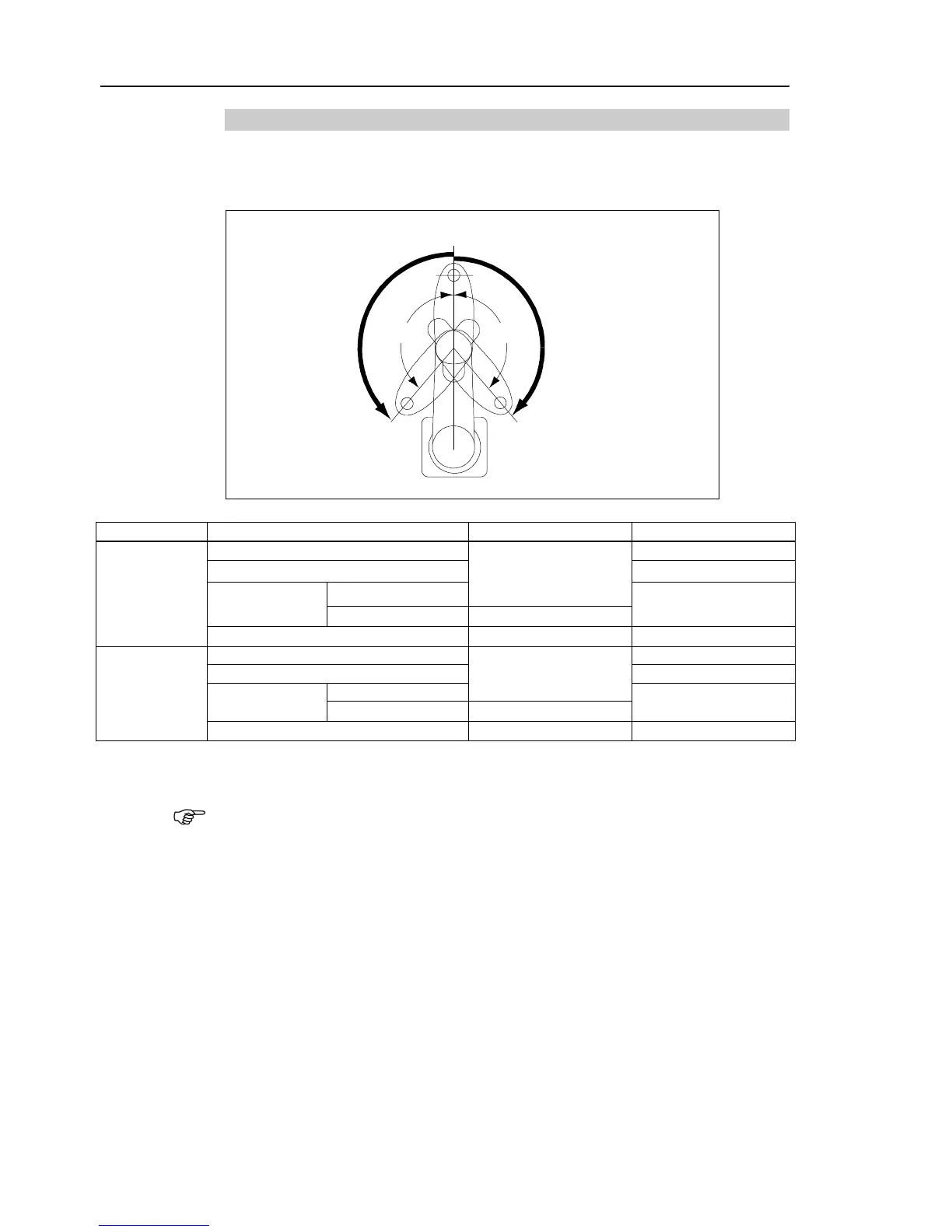
5.1.2 Max. Pulse Range of Joint #2
The 0 (zero) pulse position of Joint #2 is the position where Arm #2 is in-line with Arm #1.
With the 0 pulse as a starting point, the counterclockwise pulse value is defined as the
positive (+) and the clockwise pulse value is defined as the negative (-).
B
B
0 pulse
A
A
Model
Table Top Mounting
Ceiling, Wall Mountings
A: Max. Motion
Range
G10-65***
±152.5 degrees
±130 degrees
G10/G20-85*S*, D*
±
152.5 degrees
G10/G20-85*C*,
P*, D* bellows
Z: 0 to 360
±151 degrees
Z: 360 to 390
±151 degrees
G20-A0***
±152.5 degrees
±152.5 degrees
B: Max. Pulse
Range
G10-65***
±2776178
±2366578
G10/G20-85*S*, D*
±2776178
G10/G20-85*C*,
P*, D* bellows
Z: 0 to 360
±2748871
Z: 360 to 390
±2748871
G20-A0***
±
2776178
±
2776178
The bellows for G10/G20-***D are options at shipment.
In the range Z: –360 to –390 mm, the area is limited by interference of the Manipulator
body and the arm.
F
NOTE

Table of Contents

Related product manuals