Maintenance 10. Ball Screw Spline Unit
198 G10 / G20 Rev.20
10.2 Replacing the Ball Screw Spline Unit
The replacement procedure of the ball screw spline unit for G10 series and G20 series are
different.
Maintenance
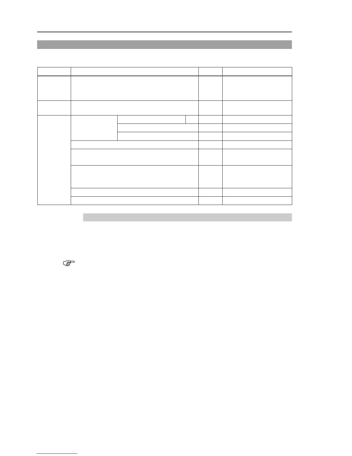
parts
Ball Screw Spline Unit 1
Each manipulator model
(Refer to Maintenance:
Grease
For Ball Screw Spline Unit (AFB grease)
width across flats: 1.5 mm
Cross-point screwdriver 1
Only for Cleanroom-model
G10 Belt tension: 130N, 160N
(13.3 kgf, 16.3 kgf)
G20 Belt tension: 130N, 200N
Suitable cord (Length about 1000 mm)
10.2.1 Replacing the Ball Screw Spline Unit: G10
A brake is mounted on the motor of Joints #3 and #4 to prevent the shaft from moving
down due to the weight of the end effector while the power to the Controller is OFF or
while the motor is in OFF status (MOTOR OFF).
Note that the brake will not work during the replacement procedure.
Move the shaft down to its lower limit before starting the replacement procedure by
following the removal steps from (1) to (3).

 Loading...


