Setup & Operation 5. Motion Range
84 G10 / G20 Rev.20
In this example, Joint #1 is moved to the
center of its motion range
) when checking Joint #2.
is hitting the mechanical stop
s or if an error occurs after the arm hits the
mechanical stops
reset the pulse range to a narrower setting or extend the
position
s of the mechanical stops within the limit.
5.2.2 Setting the Mechanical Stop of Joint #3
This method applies only to the Standard-model Manipulator (G10/G20-***S*) and
Protected-model Manipulator (G10/G20-***D* without bellows option).
For the Cleanroom-model (G10/G20-***C*) and Protected-model (G10/G20-***D* with
bellows option)
, the motion range set with the Joint #3 mechanical stop cannot be changed.
Turn ON the Controller and turn OFF the motors using the Motor OFF command.
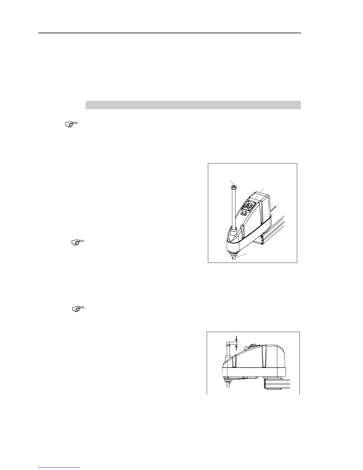
Push up the shaft while pressing the brake
release switch.
Do not push the shaft up to its upper limit
or it will be difficult for the arm top cover
to be removed. Push the shaft up to a
position where the Joint #3 mechanical stop
can be changed.
the brake release switch,
may lower and rotate due to the
weight of the end effector.
hold the shaft by hand while pressing the
button.
Lower limit mechanical stop
: 2-M5×6 set screw
Loosen the lower limit mechanical stop
A mechanical stop is mounted on both the top and bottom of Joint #3. However,
only the position of the lower limit mechanical stop on the top can be changed.
Do
not remove the upper limit mechanical stop on the bottom because the calibration
point of Joint #3 is specified using the stop.
The upper end of the shaft
mechanical stop down by the length you
want to limit the stroke.
For example, when the lower limit
mechanical stop is set at “
the lower limit Z coordinate value is
“
-420”. To change the value to “-100”,
move the lower limit mechanical stop down
320 mm”. Use calipers to measure the

 Loading...


