EasyManuals Logo

Epson G20 Series User Manual

Epson G20 Series
252 pages
To Next Page IconTo Next Page
To Previous Page IconTo Previous Page
Page #177 background imageLoading...
Page #177 background image
Maintenance 7. Arm #3
G10 / G20 Rev.20 165
7.3 Replacing the Brake
Name
Quantity
Note
Maintenance
parts
Solenoid brake
G10
1
R13B030503
G20
-
-
Tools
Hexagonal wrench
width across flats: 1.5 mm
1
For M3 set screw
width across flats: 2.5 mm
1
For M3 screw
width across flats: 3 mm
1
For M4 screw
width across flats: 4 mm
1
For M5 screw
Nippers
1
For cutting wire tie
Suitable cord (Length about 800 mm)
1
For belt tension
Material
Wire tie
3
A brake is mounted on the motor of Joints #3 and #4 to prevent the shaft from moving
down due to the weight of the end effector while the power to the Controller is OFF or
while the motor is in OFF status (MOTOR OFF).
Note that the brake will not work during the replacement procedure.
Move the shaft down to its lower limit before the replacement procedure following the
removal steps.
Joint #3 brake
Removal
(1)
Execute the removal steps from (1) to
(10) in
Maintenance 7.1 Replacing Joint #3
Motor
to remove the Joint #3 motor.
(2)
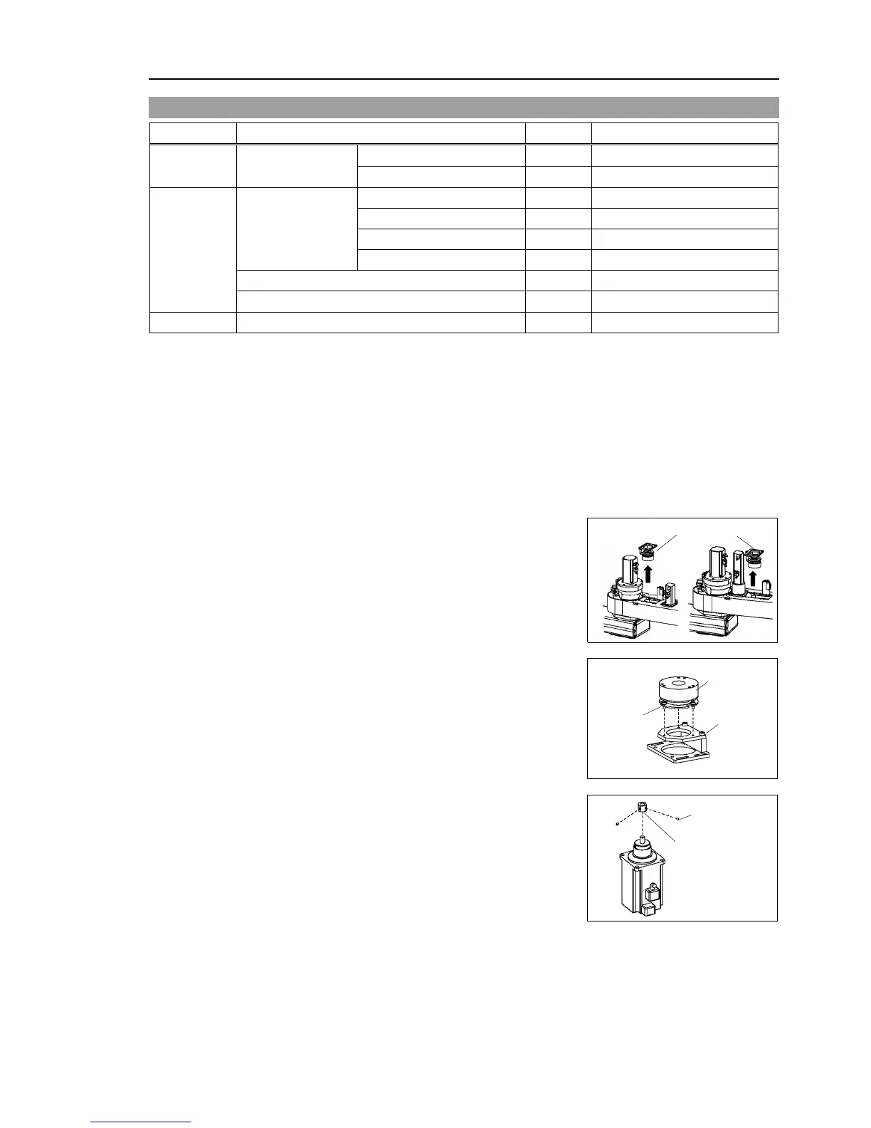
Remove the brake unit from Arm #2.
Brake unit
G20
G10
(3)
Disconnect the connector.
Connector X32
(4)
Remove the brake from the brake support.
3-M3×8
Brake
Brake
support
(5)
Remove the brake hub from the Z1 pulley.
2-M3×4
Set screw
Brake hub

Table of Contents

Questions and Answers:

Question and Answer IconNeed help?

Do you have a question about the Epson G20 Series and is the answer not in the manual?

Epson G20 Series Specifications

General IconGeneral
BrandEpson
ModelG20 Series
CategoryRobotics
LanguageEnglish

Related product manuals