Maintenance 8. Arm #4
G10 / G20 Rev.20 179
8.2.2 Replacing the Timing Belt: G20
A brake is mounted on the motor of Joints #3 and #4 to prevent the shaft from moving
down due to the weight of the end effector while the power to the Controller is OFF or
while the motor is in OFF status (MOTOR OFF).
Note that the brake will not work during the replacement procedure.
Move the shaft down to its lower limit before starting the replacement procedure by
following the removal steps.
U belt
Removal: G20
to its lower limit while pressing the brake release switch.
Be
sure to keep enough space and prevent the
hitting any peripheral
equipment.
The brake release switch is applied to both Joints #3 and #4. When the brake release
switch is pressed, the respective brakes of the Joints #3 and #4 are released
simultaneously.
shaft falling and rotating while the brake release switch is
because the shaft may be lowered by the weight of an end effector.
top cover and the arm bottom cover.
For details, refer to Maintenance: 3. Covers.
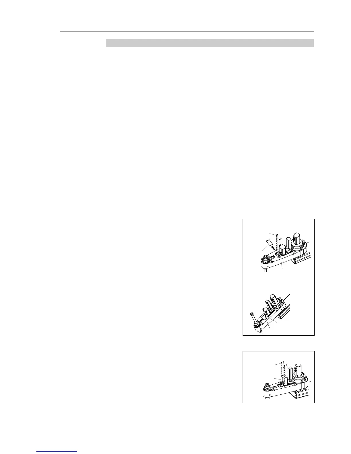
When you use the plate of 4
When you use the plate of 3
the plate mounting bolts.
Be sure to keep the connectors connected to the
battery unit.
If connectors of the battery unity are disconnected,
you need to perform calibration again.
Loosen four bolts on the Joint #3 motor unit. Slide
the Joint #3 motor unit to the end of the arm.

 Loading...


