Maintenance 8. Arm #4
178 G10 / G20 Rev.20
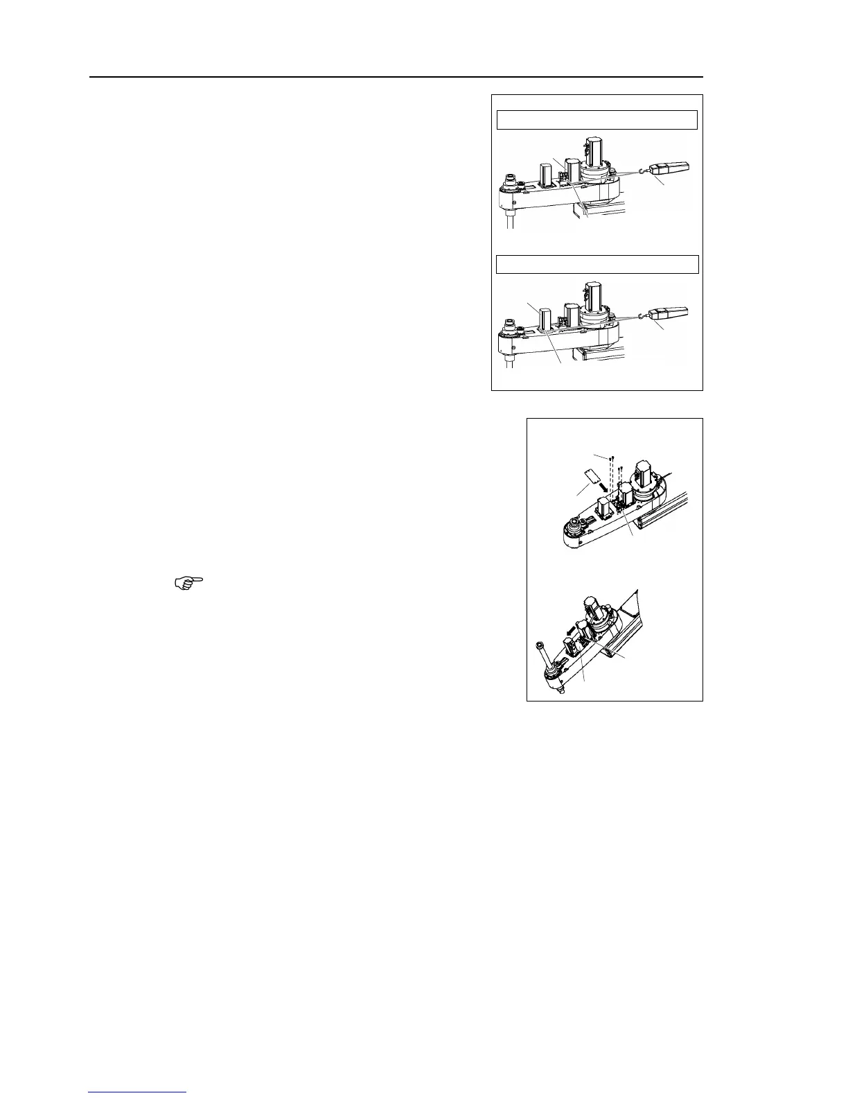
Apply the proper tension to the Z belt and U
belt, and then secure the Joint #3 motor unit
and Joint #4 motor unit.
a suitable cord or string
. Then, pull the cord using a force
or similar tool to apply the specified
tension shown in the figure on the right
Make sure that the brake cables do not touch
the pulley.
G10 : Z belt tension = 130 N (13.3 kgf)
G10 : U belt tension = 160 N
(16.3 kgf)
When you use the plate of
When you use the plate of 3
the plate with pressing it to the Joint #4 motor.
When mounting the battery unit, be sure to keep the
connectors connected to the battery unit.
If connectors of the battery unity are disconnected,
you need to perform calibration again.
top cover and the arm bottom cover.
For details, refer to Maintenance: 3. Covers.
Perform the calibration of Joint #3.
For details, refer to Maintenance: 14. Calibration.

 Loading...


