EasyManuals Logo
Home>Epson>Robotics>G20 Series

Epson G20 Series User Manual

Epson G20 Series
252 pages
To Next Page IconTo Next Page
To Previous Page IconTo Previous Page
Page #77 background imageLoading...
Page #77 background image
Setup & Operation 4. Setting of End Effectors
G10 / G20 Rev.20 65
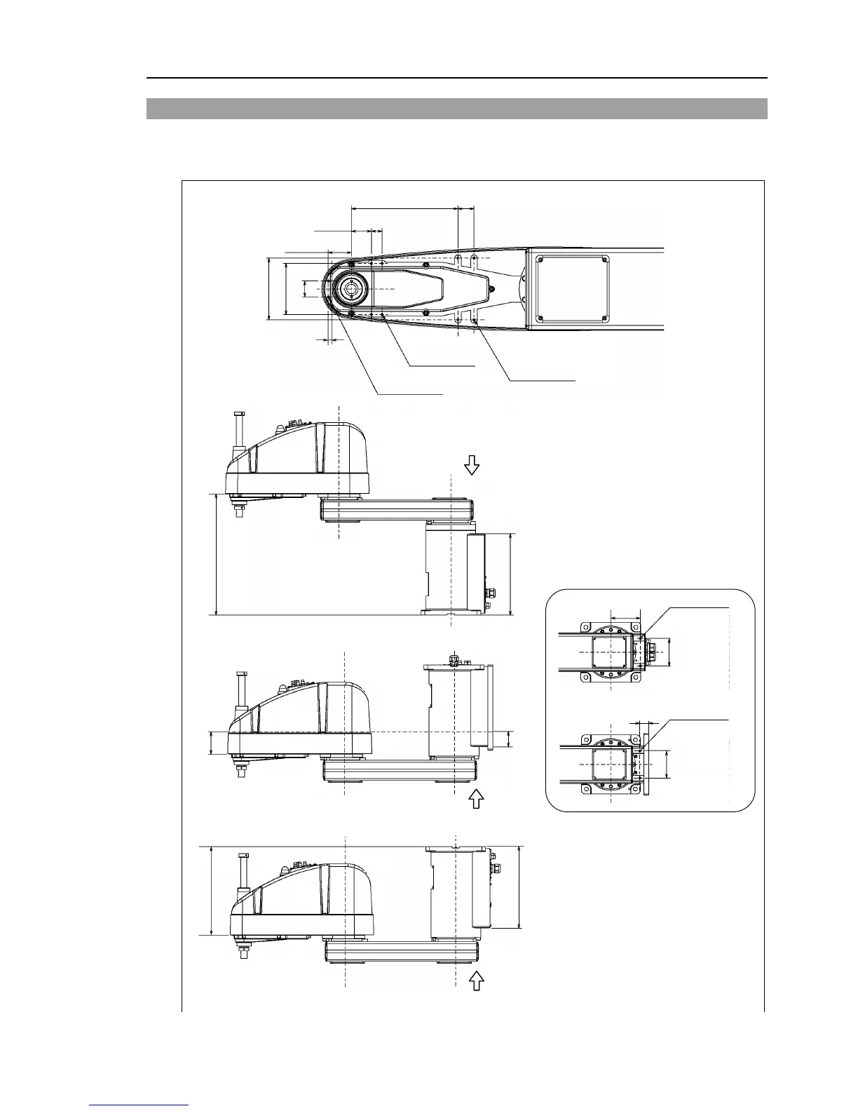
4.2 Attaching Cameras and Valves
Arm #2 has threaded holes as shown in the figure below. Use these holes for attaching
cameras, valves, and other equipment.
[Unit: mm]
A
A
30
2-M4 depth 8
4-M4 depth 8
43.5
37.5
20
4-M4 depth 8
30
116
96
2-M8 depth 16
(Mount eyebolt
at shipment)
118
110
3.5
B
2-M8 depth 16
(Mount eyebolt
at shipment)
37
110
B
A
81
Common Dimensions
Wall Mounting
Table Top Mounting
From the base
mounting face
485.5
From the base
mounting face
326
From the reference hole
110.5
From the base
mounting face
326
From the base
mounting face
355.5
Ceiling Mounting
200
For G10
-65***,G10-85*** manipulator
of S/N: 1***** or later, the form of arm
bottom is different from the others.
The additional screw holes processed on
G10-85*** are not for the end effector or
other equipments.
For the detail, refer to:
Setup & Operation 2.3.4 G10
-65***,
G10
-85***: For S/N: 1**** or later
.
F
NOTE

Table of Contents

Questions and Answers:

Question and Answer IconNeed help?

Do you have a question about the Epson G20 Series and is the answer not in the manual?

Epson G20 Series Specifications

General IconGeneral
BrandEpson
ModelG20 Series
CategoryRobotics
LanguageEnglish

Related product manuals