Maintenance 14. Calibration
G10 / G20 Rev.20 231
14.3 Accurate Calibration of Joint #2
When coordinates for the Manipulator working point require calculation, it is important
for Joint #2 to be calibrated accurately.
If the accuracy of Joint #2 is not obtained through the steps in the section Maintenance:
14.2 Calibration Procedure, follow the steps below “Calibration Using Right / Left Arm
Orientations” to accurately calibrate Joint #2.
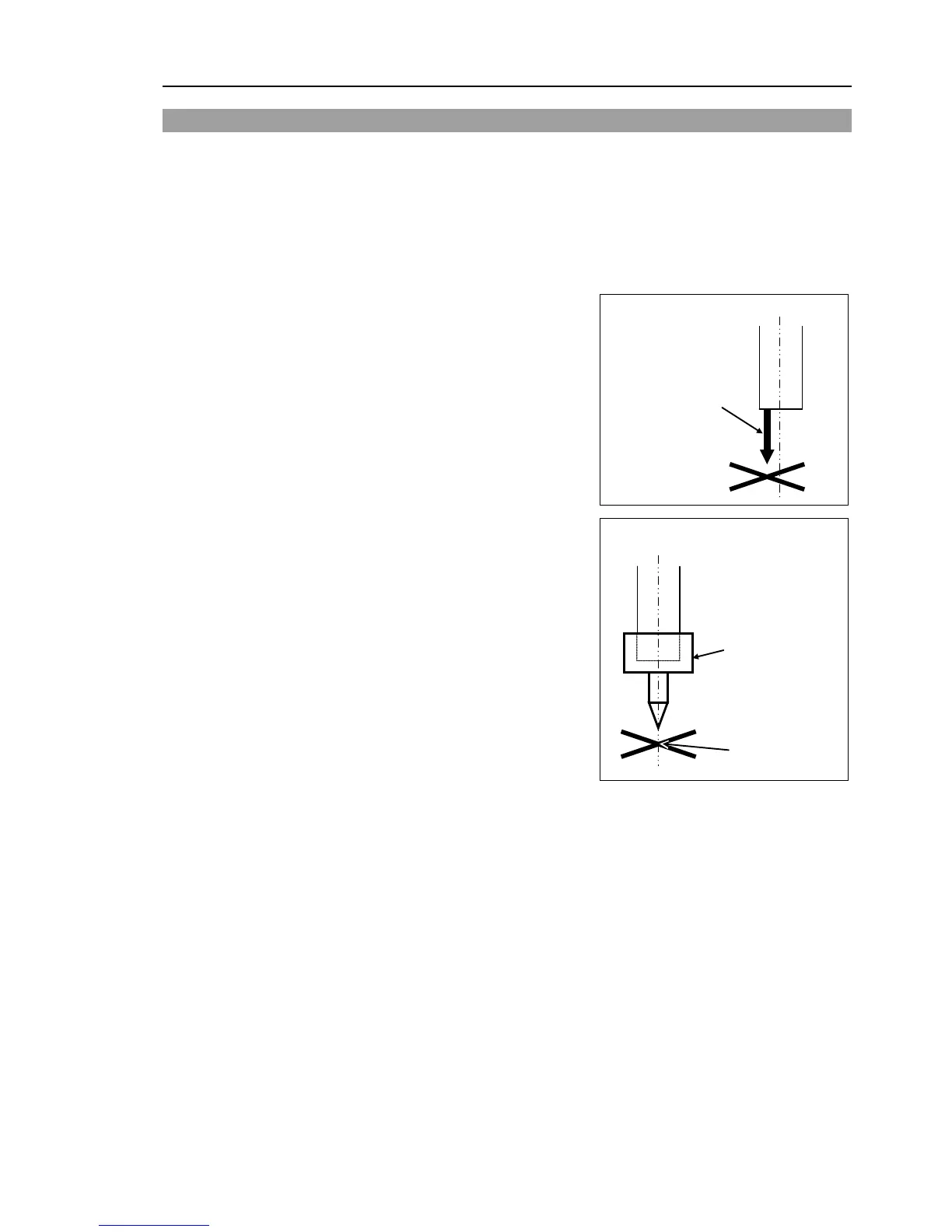
The reference point is the center of the ball
screw spline shaft during this calibration.
When there is a misalignment between the
center of the end effector and the center of the
ball screw spline shaft, remove the end effector
and perform the calibration of the shaft.
There is a misalignment
between the center of
the end effector and the
center of the shaft.
Make a calibration jig as shown in the right
figure and attach it on the end of the shaft to
make the center of the shaft clear.
Decide a target point and mark a cross (
that you can easily verify the center of the
shaft after switching the arm pose between right
and left.
Calibration jig at the
end of the shaft
(Example)
After removing the end effector and performing the
, install the end effector and
move the Manipulator to
the teaching point to verify whether there is a positional gap. If
there is a positional gap, fine
tune the installation position of the end effector and teach the
point again.
Coordinates for the working point requires calculation in the following cases:
· Teaching the working point by entering the coordinate values (MDI teaching)
· Switching the arm orientation between right and left at a given point
· Using the Pallet command
· Executing CP control (such as liner or circular interpolation)
· Using the Local command
· Pose data specified with relative coordinates <Example: P1+X(100) >
· Vision Guide camera calibrations

 Loading...


