Maintenance 10. Ball Screw Spline Unit
G10 / G20 Rev.20 199
Ball screw
spline unit
Removal : G10
Push down the shaft to its lower limit while pressing the brake release switch. Be
sure to keep enough space and prevent the
hitting any peripheral
equipment.
The brake release switch is applied to both Joints #3 and #4. When the brake release
switch is pressed, the respective brakes of the Joints #3 and #4 are released
simultaneously.
shaft falling and rotating while the brake release switch is
because the shaft may be lowered by the weight of an end effector.
and tubes from the end effector, and remove the end effector.
This step is only for Cleanroom
-model and Protected-model (C,
bellows.
For details, refer to Maintenance: 9. Bellows.
top cover and arm bottom cover.
For details, refer to Maintenance: 3. Covers.
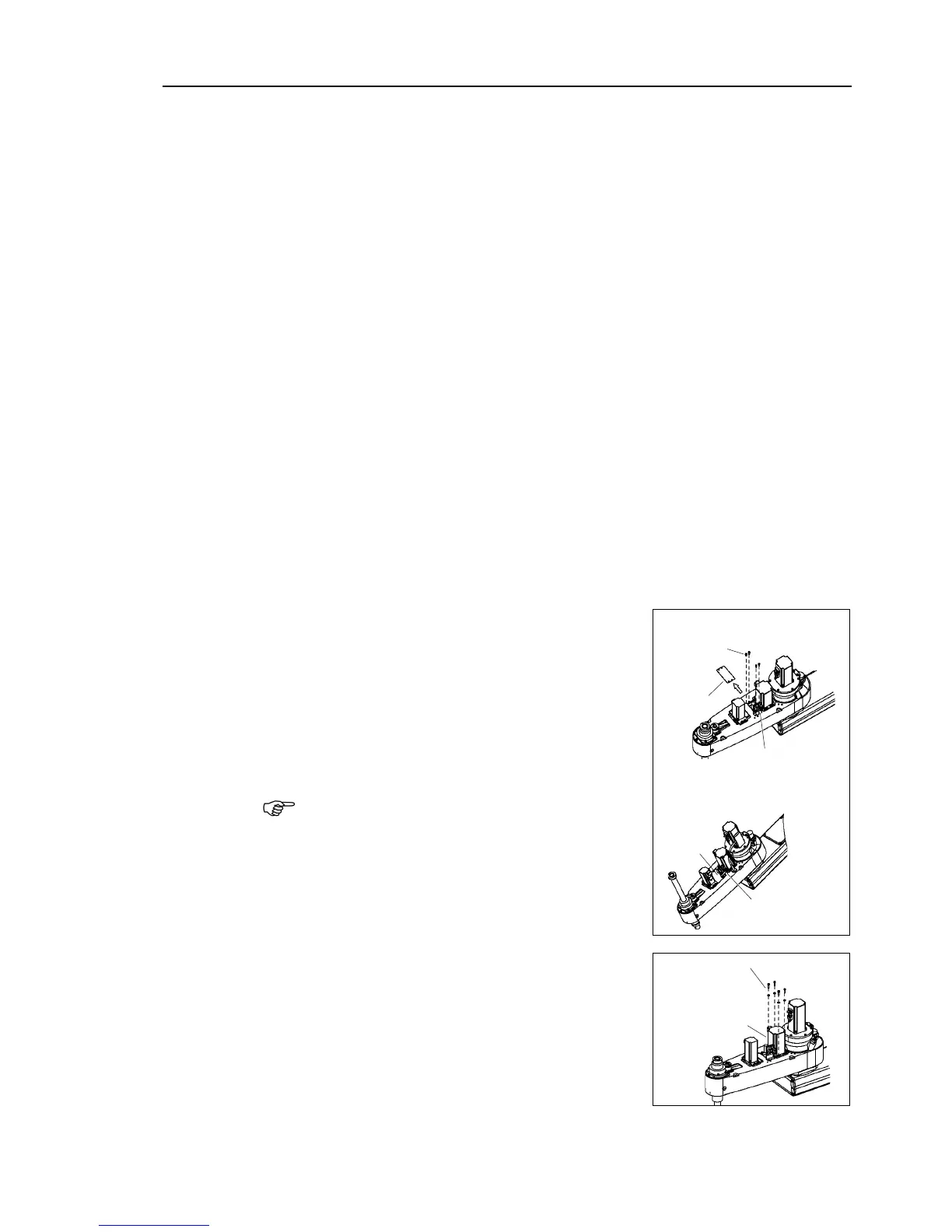
Cut off the wire tie banding motor cables to the Joint #3 motor
When you use the plate of
When you use the plate of 3
When removing the battery unit mounting bolts, be
sure to keep the connectors connected to the battery
unit.
connectors of the battery unity are
disconnected, you need to perform calibration
again.
Loosen four bolts on the Joint #3 motor unit.
Slide the Joint #3 motor unit to the end of the arm.

 Loading...


