Maintenance 6. Arm #2
G10 / G20 Rev.20 147
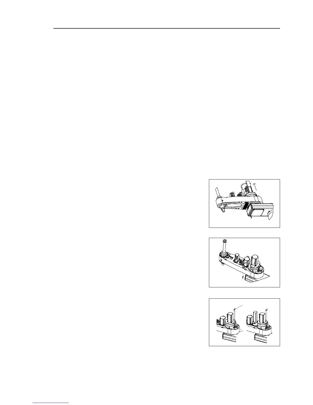
Push down the shaft to its lower limit while pressing the brake release switch.
Be sure to keep enough space and prevent
the end effector hitting any
The brake release switch is applied to both Joints #3 and #4. When the brake release
switch is pressed, the respective brakes of the Joints #3 and #4 are released
simultaneously.
shaft falling and rotating while the brake release switch is
because the shaft may be lowered by the weight of an end effector.
Remove the arm top cover.
For details, refer to Maintenance: 3.1 Arm Top Cover.
Cut off the wire tie used for binding the motor cables to the Joint #2 motor.
Disconnect the following connectors.
Connectors X221, X21 (Hold the claw to remove.)
Connector X62
This step is for the Radiating Unit:
-1 Remove the mounting bolt of the heat
sink (Hexagon socket head cap bolt
(fully threaded)) mounted
radiating unit side beneath the arm.
The radiating unit side is the right side
from the arm forefront.
(7)-2 Remove the insulation lock that secures
the plate of radiating unit and rotate the
radiating unit.
At this point, be sure to keep the plate
mounted.
 Loading...


