EasyManuals Logo
Home>Epson>Robotics>G20 Series

Epson G20 Series User Manual

Epson G20 Series
252 pages
To Next Page IconTo Next Page
To Previous Page IconTo Previous Page
Page #169 background imageLoading...
Page #169 background image
Maintenance 7. Arm #3
G10 / G20 Rev.20 157
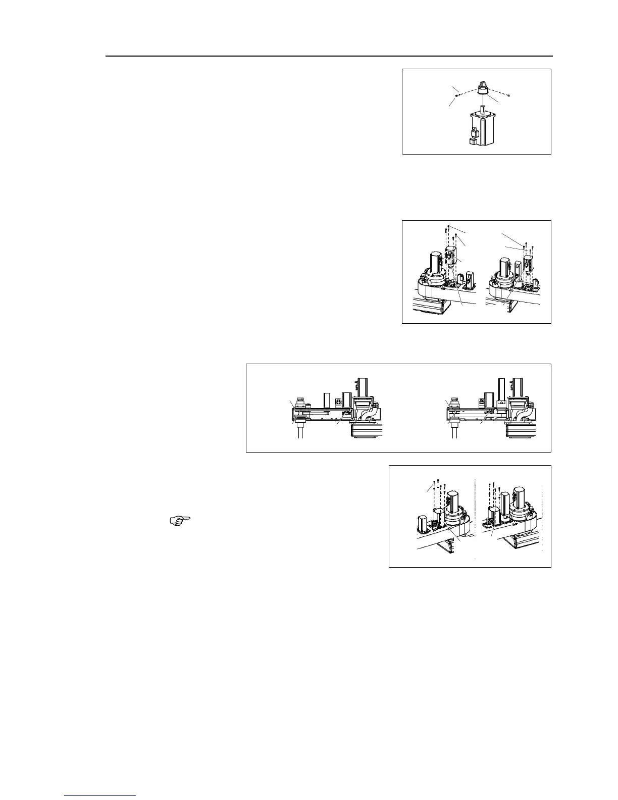
Joint #3 motor
Installation
(1)
Secure the pulley to the new motor shaft.
Be sure to fit the end face of the pulley to
the
end face of the
motor shaft.
Tighten one of the set
screws on the flat face
of the motor shaft until the screw just
touches the surface.
Insert a bushing into the other set
screw hole
to prevent damage to the motor shaft.
Then, tighten
both set screws.
M4 bushing
2-M4×5
set screw
Pulley
(2)
Align the brake disk to the hub and mount
the Joint #3 motor to the plate.
Be sure to pass the motor through the belt.
Place the Joint #
3 motor to the plate so that
the motor cable faces toward the
left from
the end
of Arm #2.
2-M5×20
Joint #3 motor
2-M5×10
G10
G20
Cable
(3)
Place the Z belt around the Z1 pulley and
the Z2 pulley so that the gear grooves of
the belt are fit into those of the pulleys
completely.
Z belt
Z2 pulley
Z1 pulley
G10
Z belt
Z2 pulley
Z1 pulley
G20
(4)
Loosely secure the Joint #3 motor unit to
Arm
#2.
Loosely secure the Joint #3 motor unit to
Arm
#2 so that the motor unit can be
moved by hand
, and it will not tilt when
pulled. I
f the unit is secured too loose
or too tight
, the belt will not have the
proper tension.
4-M4×15
+ Washer
Joint #3
motor unit
G10
G20
NOTE

Table of Contents

Questions and Answers:

Question and Answer IconNeed help?

Do you have a question about the Epson G20 Series and is the answer not in the manual?

Epson G20 Series Specifications

General IconGeneral
BrandEpson
ModelG20 Series
CategoryRobotics
LanguageEnglish

Related product manuals