EasyManuals Logo
Home>Epson>Robotics>G20 Series

Epson G20 Series User Manual

Epson G20 Series
252 pages
To Next Page IconTo Next Page
To Previous Page IconTo Previous Page
Page #185 background imageLoading...
Page #185 background image
Maintenance 8. Arm #4
G10 / G20 Rev.20 173
Joint #4 motor
Installation: G20
(1)
Mount the ring to
the Joint #4 motor.
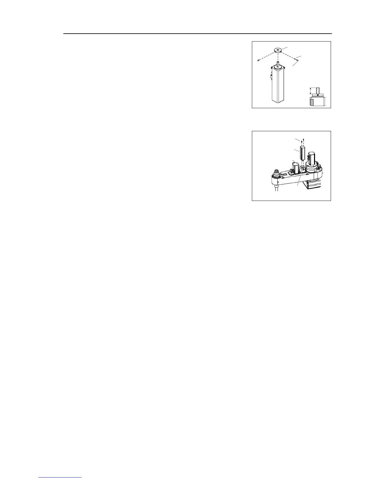
Be sure to fit the end face of the
ring 16.5 mm
from
the end face of the motor shaft.
Tighten one of the set
screws on the flat face of the
motor shaft until the screw just
touches the
surface.
Insert a bushing into the other set
screw hole to
prevent damage to the motor shaft.
Then, tighten
both set
screws.
Bushing
Ring
2-M3×8
set screw
16.5 mm
(2)
Secure the Joint #4 motor to the reduction gear
unit
so that the Joint #4 motor cable faces toward
the
left from the end of Arm #2.
2-M4×10
Joint #4 motor
Reduction
gear unit
M3×10
(Securing the motor shaft)
(3)
Secure the motor shaft to the reduction gear unit.
(4)
Connect the connectors X241, X41, and X64.
(6)
Re
-bundle the cables in their original positions with a wire tie
removed in the removal
procedure
.
Do not
allow unnecessary strain on the cables.
(7)
Install the arm
top cover and the arm bottom cover.
For details, refer to Maintenance: 3. Covers.
(8)
Perform the calibration of Joint #4.
For details on the calibration method, refer to Maintenance: 14. Calibration.

Table of Contents

Questions and Answers:

Question and Answer IconNeed help?

Do you have a question about the Epson G20 Series and is the answer not in the manual?

Epson G20 Series Specifications

General IconGeneral
BrandEpson
ModelG20 Series
CategoryRobotics
LanguageEnglish

Related product manuals