EasyManua.ls Logo

Epson G20 Series

Epson G20 Series
252 pages
To Next Page IconTo Next Page
To Previous Page IconTo Previous Page
Loading...
Setup & Operation 1. Safety
G10 / G20 Rev.20 11
To check brake problems, refer to the following manuals.
Manipulator Manual Maintenance
2.1.2 Inspection Point - Inspection While the Power is ON
(Manipulator is operating)
Safety and Installation
5.1.1 Manipulator
- Inspection While the Power is ON (Manipulator is operating)
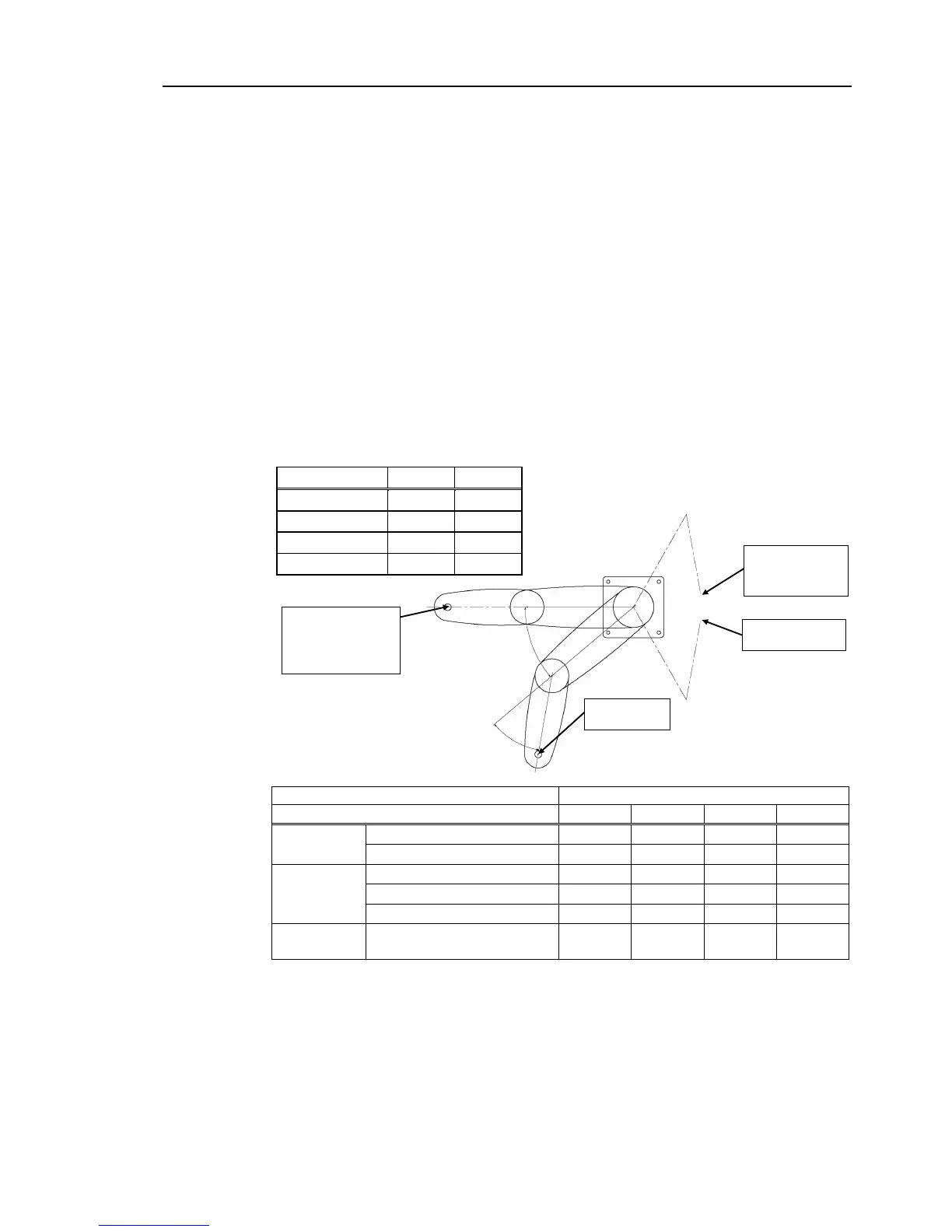
Free running distance in emergency
The operating Manipulator cannot stop immediately after the Emergency Stop switch is
pressed.
The free running time/angle/distance of the Manipulator are shown below. However,
remember that the values vary depending on following conditions.
Weight of the end effector Weight of work piece Operating pose
Weight Speed Accel etc.
Conditions for Measurement
G10
G20
Accel Setting
100
100
Speed Setting
100
100
Load [kg]
10
20
Weight Setting
10
20
Joint #1
Start point of
operation
Target point
Stop point
Joint #2
Point where the
emergency stop
signal is input
Controller
RC700-A
Manipulator
G10-65***
G10-85***
G20-85***
G20-A0***
Free running
time
Joint #1 + Joint #2 [s]
0.5
0.8
0.9
0.7
Joint #3 [s]
0.3
0.3
0.3
0.3
Free running
angle
Joint #1 [deg.]
40
85
90
75
Joint #2 [deg.]
65
75
70
65
Joint #1 + Joint #2 [deg.]
105
160
160
140
Free running
distance
Joint #3 G10/G20-**1** [mm]
G10/G20-**4**
80 80 140 140

Table of Contents

Related product manuals