Setup & Operation 2. Specifications
G10 / G20 Rev.20 39
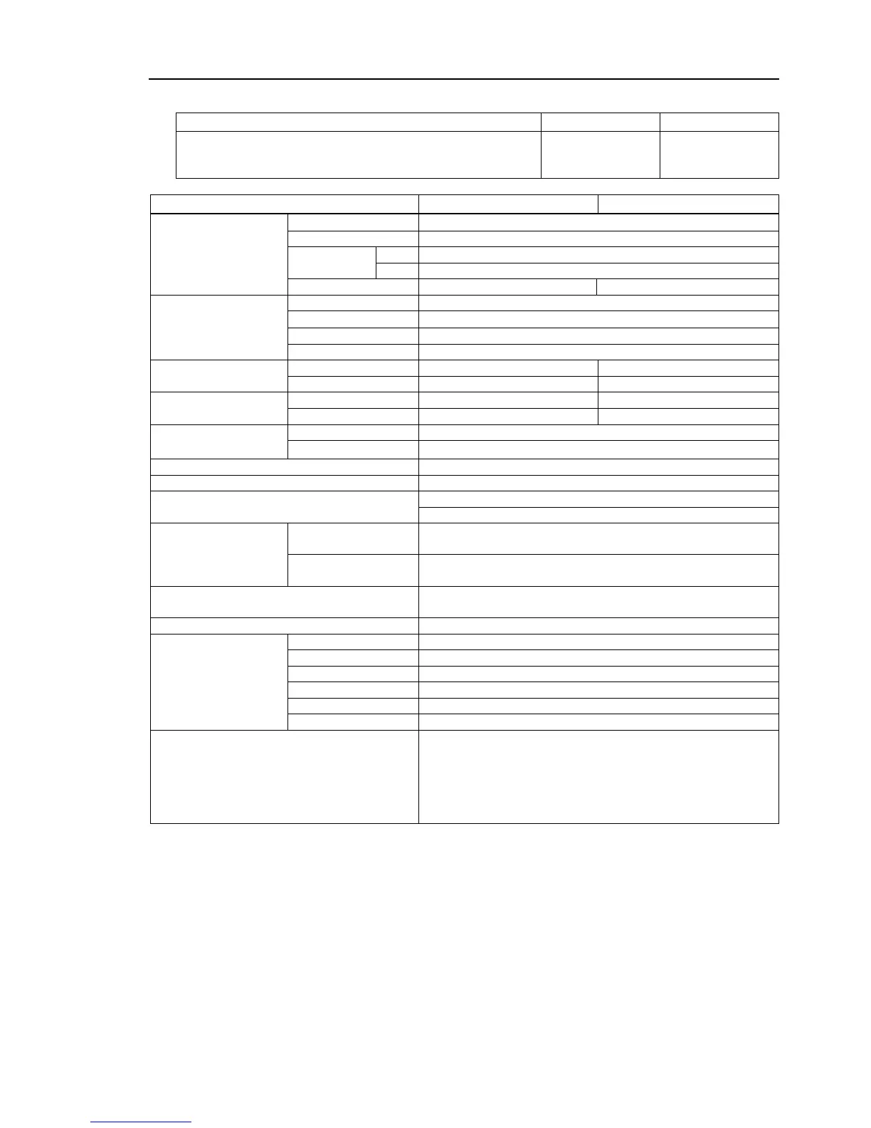
*a : The Joint #2 values for the following manipulators
G10/G20-85C, P, D with bellows option (Z: -360 to -390 only)
G10/G20-85CW, PW, DW with bellows option
G10/G20-85CR, PR, DR with bellows option
Joint #4 allowable
moment of inertia *4
Installed wire for customer use
24 (15 pin + 9 pin : D-sub)
Installed pneumatic
tube for customer use
2 pneumatic tubes (ø6 mm) : 0.59 MPa (6 kgf/cm
2
: 86 psi)
2 pneumatic tubes (ø4 mm) : 0.59 MPa (6 kgf/cm
2
: 86 psi)
Environmental
requirements
5 to 40°C (with minimum temperature variation)
Ambient relative
humidity
10 to 80% (no condensation)
Equivalent continuous A-weighted sound
pressure level *5
Assignable Value
( ) Default values
0,400 to (10,400) to 20,400
Safety standard
CE Marking : EMC Directive, Machinery Directive,
RoHS Directive
KC Marking / KCs Marking
UL standards (In case of UL specification):
UL1740, ANSI/RIA R15.06, NFPA 79
*1: The exhaust system in the Cleanroom-model Manipulator (G10/G20-*
**C*) draws air from the base
interior and arm cover interior.
A crack or other opening in the base unit can cause loss of negative air pressure in the outer part of the
arm, which can cause increased dust emission.
Do not remove the maintenance cover on the front of the base.
Seal the exhaust port and the exhaust tube with vinyl tape so that the joint is airtight.
If the exhaust flow is not sufficient, dust particle emission may exceed the specified maximum level.

 Loading...


