EPSON Stylus COLOR 670 Revision A
Disassembly and Assembly Disassembly 79
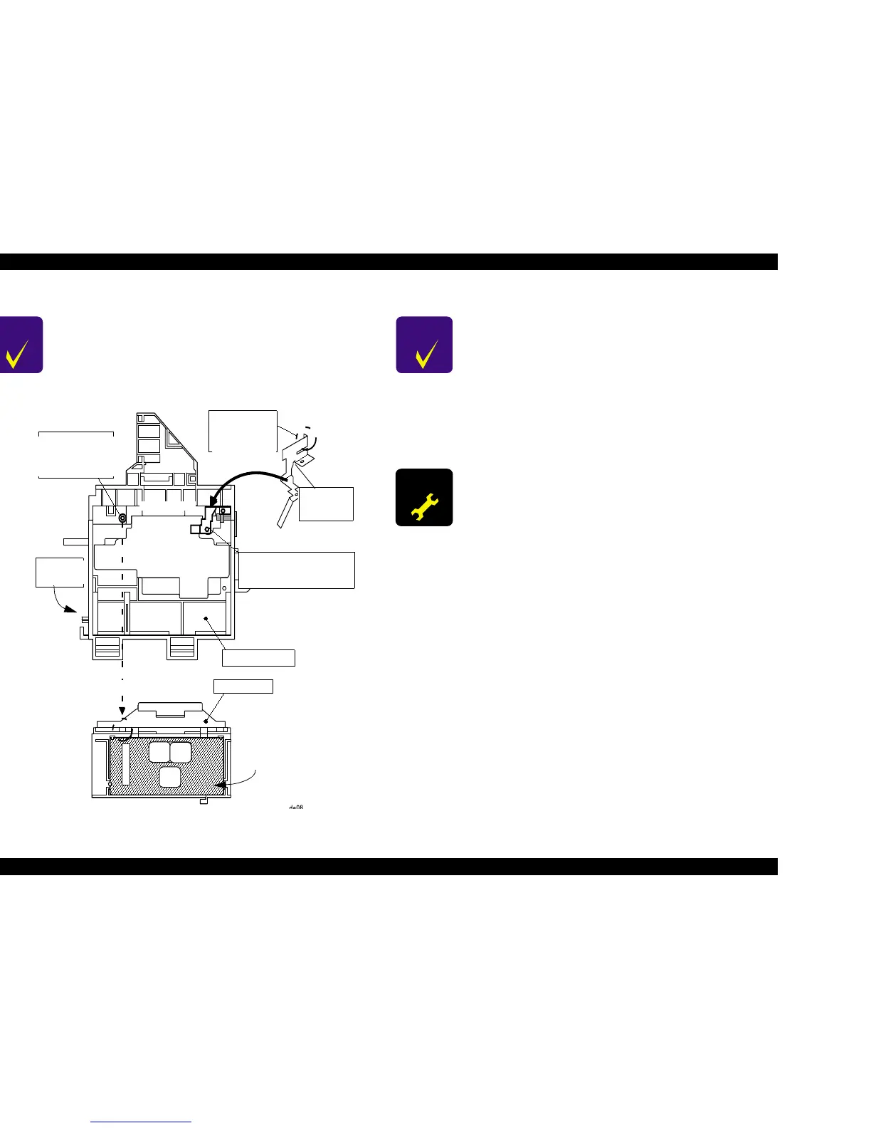
Figure 4-10. Printhead Installation
CHECK
POINT
n Be sure that the Head Grounding Plate is installed to the
carriage correctly. (There are 2 position marking pins on
the carriage.)
n After installing the printhead to the carriage, make sure
that the position marking pin at the carriage side is
correctly located into the cutoff of the printhead.
Printhead Back View
Printhead
Head
Grounding
Plate
This protrusion
must be in the U
groove of the
printhead.
This part
should contact
with the CR
Bushing.
These protrusions of CR
must be in the holes of the
head grounding plate.
CR Assembly
Printhead
Printhead
Pinthead
Top View
CHECK
POINT
n Install a new cartridge before sending back the printer to
the user, since the ink cartridge once taken out can not
be used again.
n Installation of I/C must be carried out by I/C replacement
sequence. Otherwise, ink may not be ejected properly.
n When you return the printer to the user, pack the printer
with ink cartridges installed.
n When you return the printer to the user, make sure CR
Lock Lever is set properly and then pack the printer.
ADJUSTM ENT
REQUIRED
Perform the following adjustment after replacing the
printhead in the order below;
1. Ink Initial Charge (See “Initial Ink Charge” on page 118)
2. Head ID Input (See “Head ID Input” on page 107)
3. Head Angular Adjustment (See “Head Angular
Adjustment” on page 109)
 Loading...


