
A
Ashley ShawAug 17, 2025
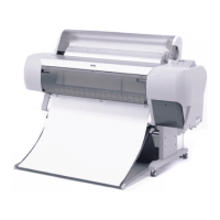
What to do if my Epson StylusPro 10000 Printer says PAPER JAM?
- KKerri HolmesAug 17, 2025
If your Epson Printer displays a PAPER JAM error, it means paper has been detected by both the rear and front paper sensors, or there's an over drive current or mis-synchronization of the CR motor. Remove the jammed paper, then turn the power off and on to reboot the printer.


