40
Figure 4-55.
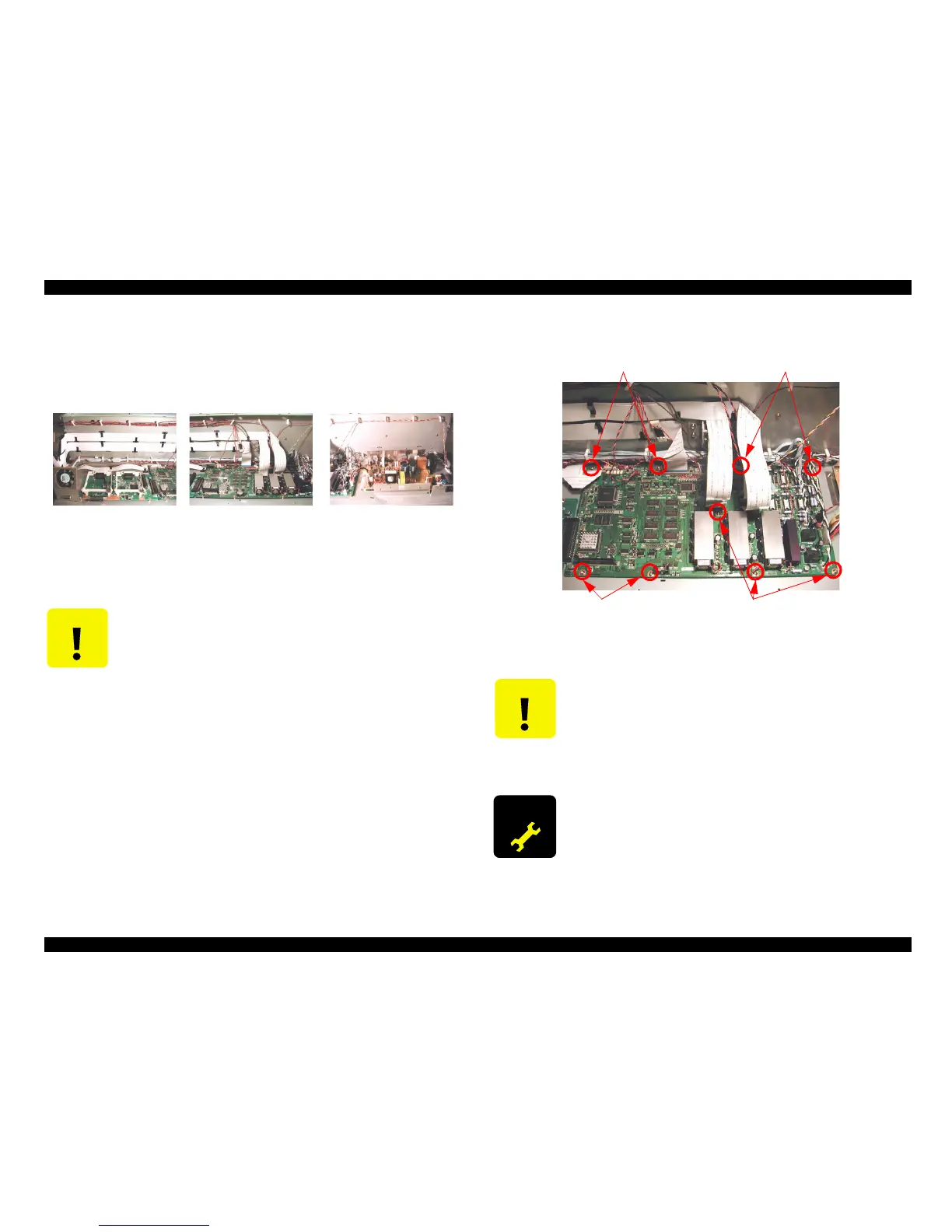
4. Remove nine screws (CP(W) M3x6) securing the C362DRV board and remove the
board.
Figure 4-56.
C A U T I O N
When removing or replacing the FFC cables, always do so carefully.
Tearing or folding of the leads can damage the circuit boards. Check
the leads and never insert at an angle.
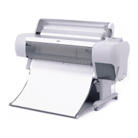
(Clamp location)
(Power Board area)
(C362DRV Board area)
(C362MAIN Board area)
C A U T I O N
When removing/re-inserting the flat-cable (FFC) from/to a connector,
make sure to pull/insert the cable straight. Otherwise, internal contact
of the connector may be damaged and this causes a short-circuit to
destroy the electrical circuitries.
Lithium battery (CR2032:3V) is installed on the C362DRV board. Do
not short the C362DRV board with metal or conductive materials.
A D J U S T M E N T
R E Q U I R E D
After replacing the C362DRV board, various adjustments are
required. For details about these adjustments, refer to Chapter 5,
Adjustment.
Screw
Screw
Screw
Screw
 Loading...


