Appendix D-18 Product Overview Rev. A
Confidential
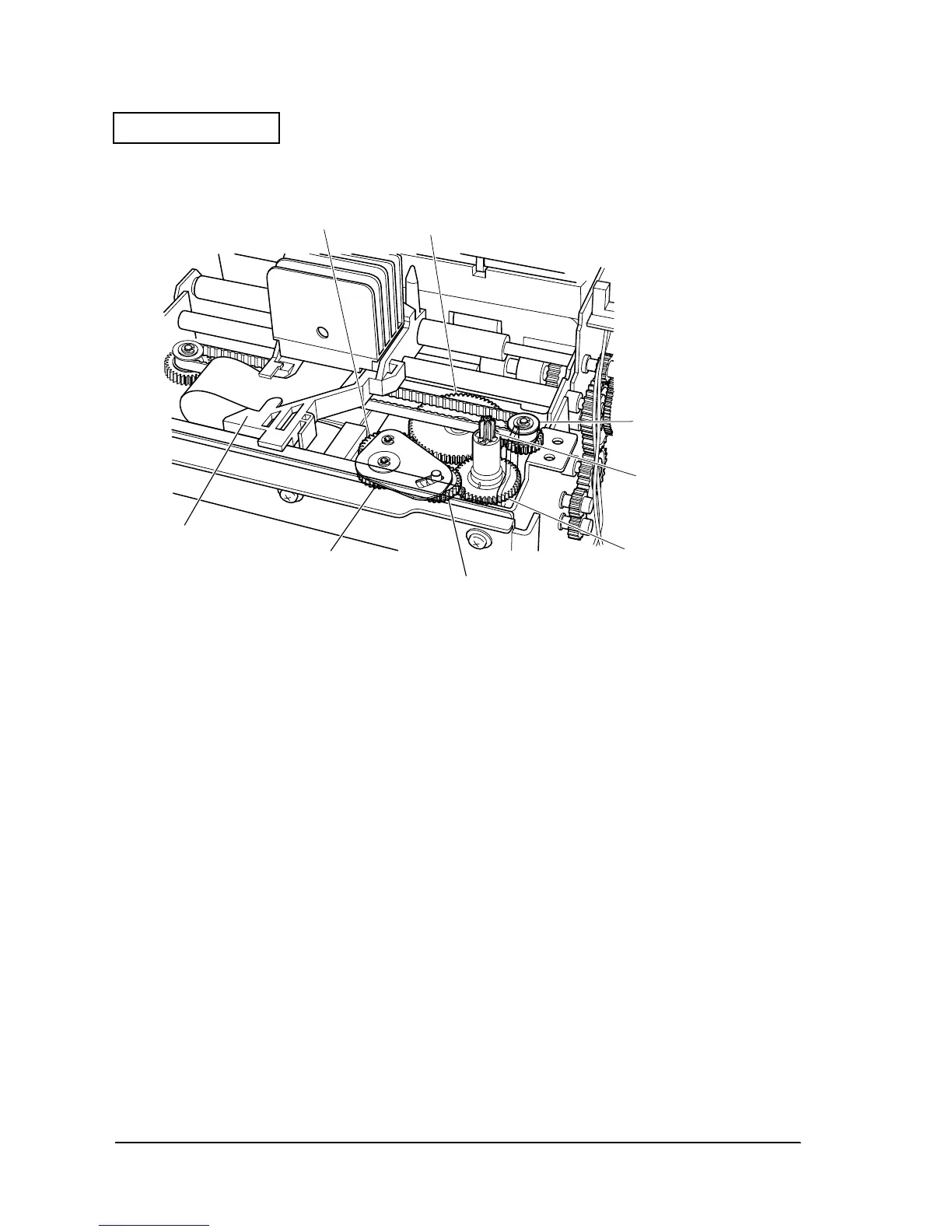
This ribbon feed mechanism only feeds the ribbon when the head carriage assembly is moved
from the right side to the left side.
Figure D-24
Ribbon feed operation
When the head carriage assembly is moved from the right side to the left side by the carriage
motor, the carriage transmission pulley is rotated in the direction indicated by arrow A in the
figure on the next page. This driving force rotates the ribbon drive gear (planetary gear) in the
direction indicated by arrow B via the transmission gear and ribbon reduction gear. At this
time, the ribbon drive plate rotates in the direction indicated by arrow C around the ribbon
reduction gear rotation shaft until the ribbon drive gear meshes with the ribbon intermediate
gear.
Meshing of these gears results in the driving force of the ribbon drive gear being transmitted to
the ribbon take-up gear via the ribbon intermediate gear, rotating the ribbon take-up shaft
mounted at the top in the direction indicated by arrow D.
The ribbon is fed when the ribbon feed roller in the ribbon cassette meshes with this ribbon take-
up shaft.
On the other hand, when the head carriage assembly is moved from the left side to the right side,
the carriage transmission pulley is rotated in the direction indicated by arrow E, and the ribbon
drive plate rotates in the direction indicated by white arrow F around the ribbon reduction gear
rotation shaft. Consequently, the ribbon drive gear and ribbon intermediate gear no longer
mesh, and the ribbon take-up gear remains in place, and the ribbon is not fed.
Ribbon reduction gear
transmission gear
Carriage transmission
pulley
Ribbon take-up shaft
Ribbon take-up gear
Ribbon intermediate gear
Ribbon drive gear
Head carriage set
 Loading...


