Disassembly and Assembly 2-24 Rev. A
Confidential
Assembling the Thermal Mechanism
Pre-assembly Procedures
Pre-assembly of the N. E. Detector Assembly]
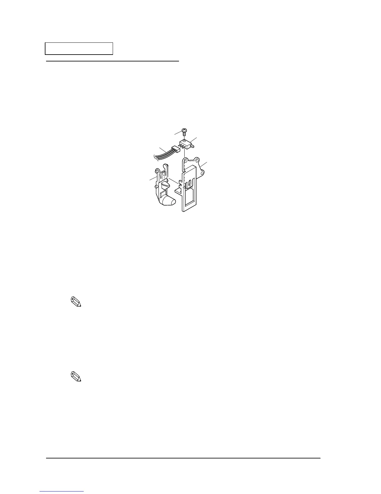
1. Attach the N. E. detector to the N. E. detector holder.
2. Fit the micro switch to the N. E. detector holder with one screw.)
Figure 2-21
Pre-assembly of the Paper Cutter Assembly Cover B]
1. Gather the four lead wires for the paper cutter and pass them through the guard tube.
2. Pass each of the four lead wires for the paper cutter through D shield tube.
3. Solder the two write lead wires to the legs of the micro switch. Separate the shield tubes
from the pins.
Note:
Check that the soldering is secure.
4. Position the two paper cutter lead wires.
5. Solder the lead wires to the legs of the paper cutter motor. Separate the shield tubes from
the pins. Install the motor so that the label side is facing upward, and solder the black lead
wire to the (-) and the red lead wire to the (+) sides where they are marked. Be careful of the
direction of the soldering.
Note:
Check that the soldering is secure.
6. Move the two shield tubes toward the two micro switch pins and the two motor pins. The
pins should be covered by the shield tubes.
504 screw(C.B.B-tite,2X8)
542 Micro switch
508 N.E. detector holder
543
Cover open detector
lead wire
509
N.E. detector lever
 Loading...


