Rev. A Disassembly and Assembly 2-3
Confidential
TM-H6000/H6000P Service Manual
Assembling the Mechanism for the Slip Printer
Pre-assembly Procedures
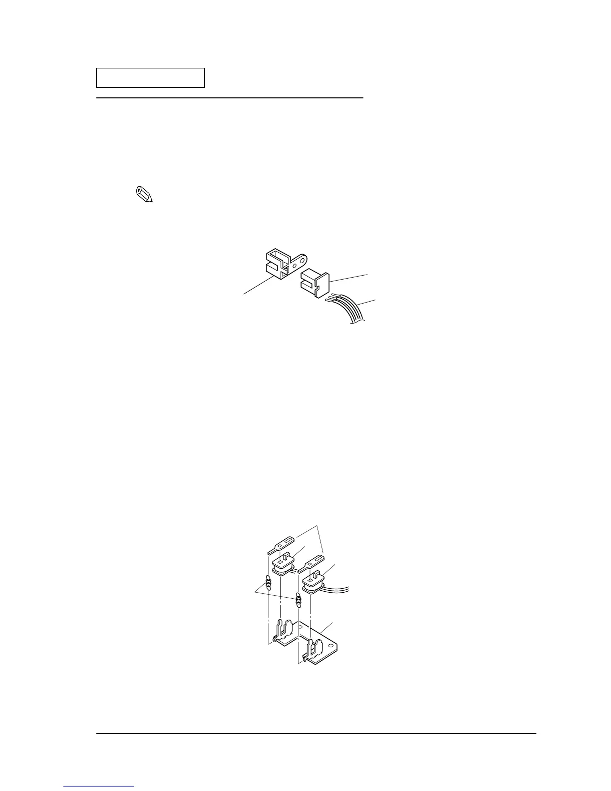
Pre-assembly of the slip BOF Detector Assembly
1. Solder lead wires C, D, E to the slip B. O. F. detector assembly.
Note:
Check that the soldering is secure.
2. Insert the slip B. O. F. detector into the slip insertion detector holder.
Figure 2-1
Pre-assembly of the Lever Drive Coil Assembly
1. Attach coil lever drive A, B to the paper feed steel core. The rack for coil lever drive A and B
should face upward. Check the direction for attachment.
2. Fasten the paper feed trigger suction plate to the coil lever drive. Check the direction for
attachment.
3. Hook the paper feed trigger claw spring 3 onto the paper feed steel core and paper feed
trigger suction plate. One side of the paper feed trigger claw spring 3 is single and the other
side is double. Attach the double side onto the paper feed trigger suction plate.
4. Lubricate the area contacting the trigger suction plate coil lever and the area contacting the
paper feed steel core (Eight places). See Appendix G for a lubrication diagram.
Figure 2-2
668
Slip B.O.F. detector
assembly
605Slip insertion detector holder
707 Lead wire (type C)
708 Lead wire (type D)
709 Lead wire (type E)
620 Lever drive coil (type A)
621 Lever drive coil (type B)
667
Lever coil mounting plate
sub assembly
696 Paper feed trigger attraction plate
695
Paper feed
trigger claw spring
608
 Loading...


