Rev. A Product Overview Appendix D-69
TM-H6000/H6000P Service Manual
Confidential
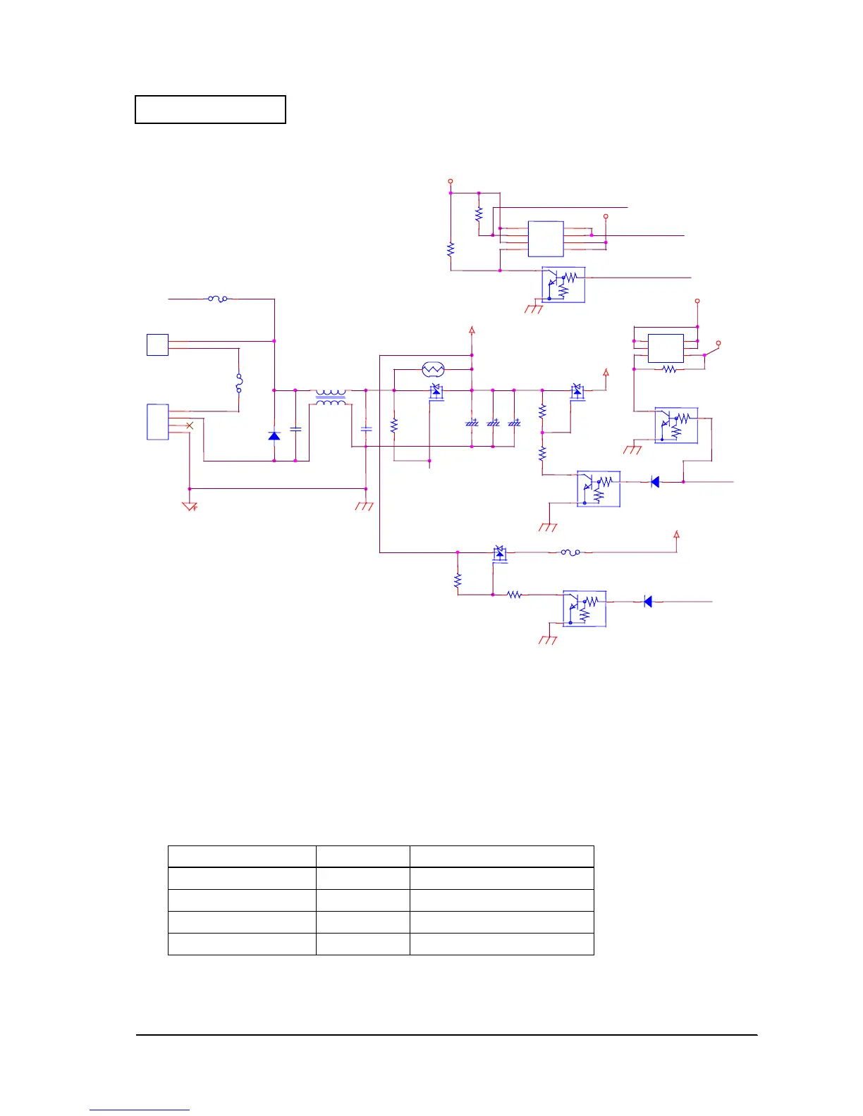
Figure D-67
Control Panel Function
This printer has four LEDs and two input switches.
Display Functions
The LED displays are shown below. The CPU (U3) controls them.
TableD-16 Types of displays
Circuit Signal Color Application
LED_POWER Green Lights during normal operation
LED_ERROR Red Indicates printer error
LED_PAPER Red Indicates printer paper status
LED_SLIP Green Indicates slip selection
24V(DM)
24VB
24VC
24VA
VCC
VCC-PWR2
VCC
VCC-PWR
SIN2-1
SIN2-1
MIN1
24VSW1
FG
PIN1
24VSW2
24VSW1
VCC_SEN
SEN_PWR
CN18
1
2
3
SH
F1
C41
CN29
1
2
Q24
Q61
TH1
Q46
Q45
R96
R244
R176
C44C43C42
D16
Q59
D1
D2
G S
D3
D4
Q17
R243
F2
F3
R177
D45
C40
L3
R94
D22
Q60
Q44
S1
G1
S2
G2 D2
D2A
D1A
D1
Q51
R207
R208
 Loading...


