Disassembly and Assembly 2-26 Rev. A
Confidential
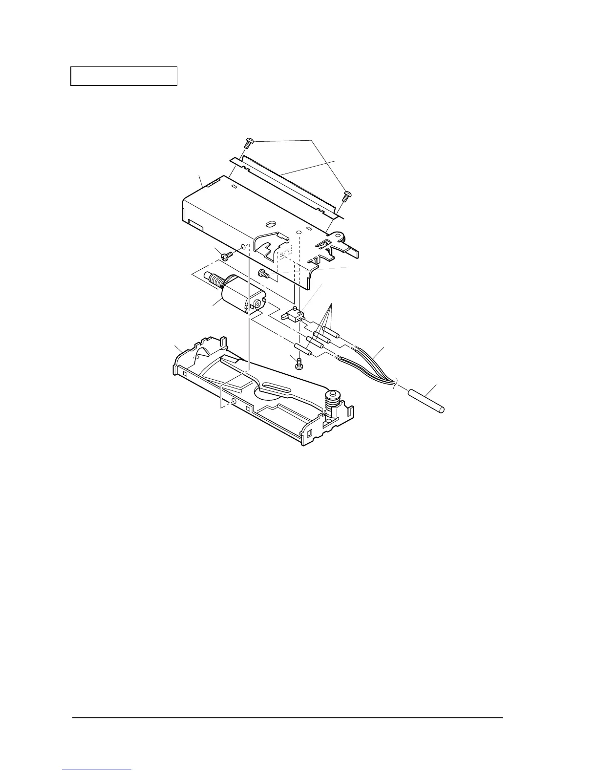
17. Tight on the screw on the paper cutter assembly frame and the paper cutter assembly cover
B.
Figure 2-22
Assembly of the Thermal Mechanism
1. Snap fit the paper detector assembly to the paper holder.
2. Attach the damper plate to the paper holder. Install on the paper holder rack.
3. Use double-sided tape to affix the relaxation plate fixing plate to the paper holder and fasten
the relaxation plate.
4. Attach the N. E. detector unit to the left frame. Install so that the hexagonal nut position is at
the top.
5. Temporarily tighten the reduction gear shaft to the left frame.
6. Attach the left frame to the paper holder with two screws.
7. Using two screws, attach the frame plate and the right frame to the paper holder.
548
screw(C.B.,2X2.5)
548
screw(C.B.,2X2.5)
530 Manual cutter A
546
Paper cutter cover
assembly
540
screw(C.B.S-tite F,3X6)
540
screw(C.B.S-tite F,3X6)
535
Micro switch
532 Cover tube
534
Paper cutter lead wire
528
Paper cutter frame
assembly
549
Switch
screw
533
Guard tube
 Loading...


