Rev. A Troubleshooting 1-11
TM-H6000/H6000P Service Manual
Confidential
Test Points on the Main Circuit Board Unit
Power Supply Line Check
After a main board feilure, one basic method for diagnosing the cause of the failures on the main
circuit board unit is to check the power supply line. Use the following table to check the power
supply line. First, check step number 1, and proceed to the next step if that is not the problem.
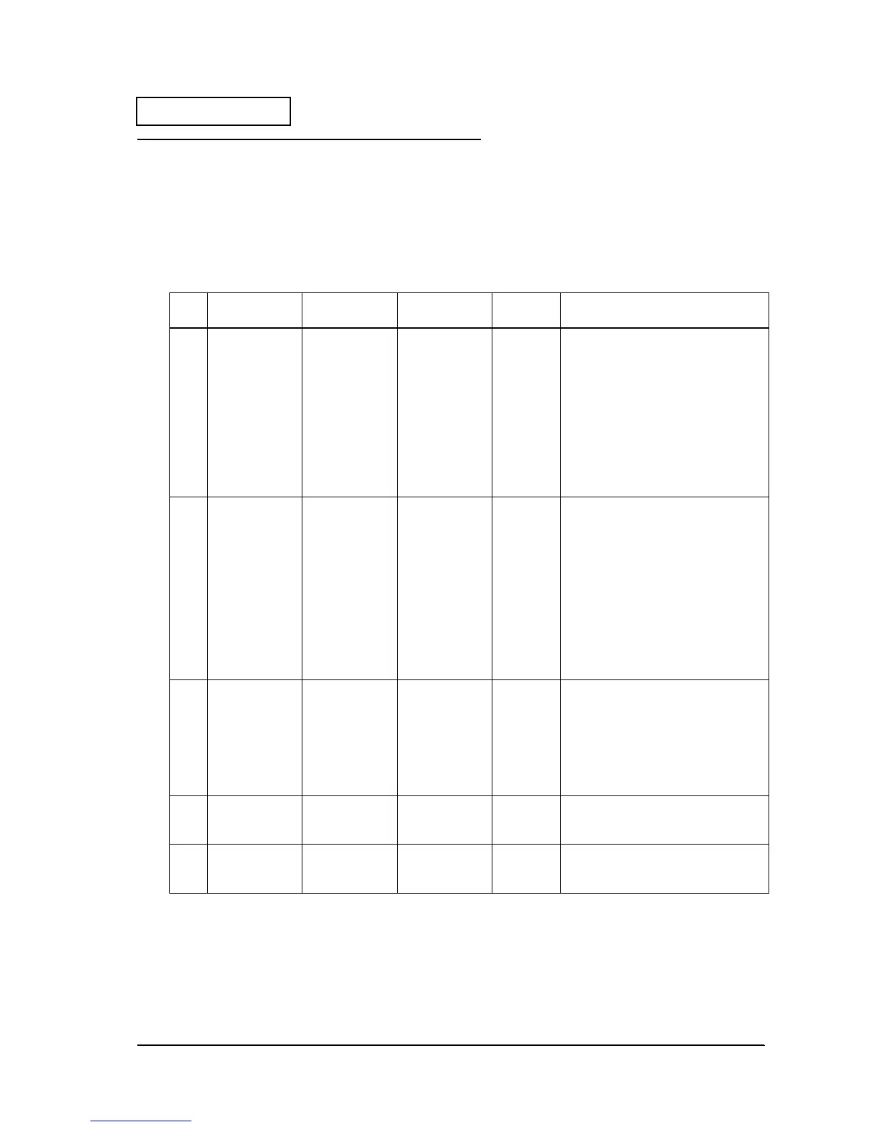
Table1-3 Checking the power supply line
Step
# Type of Voltage
Location of
Measurement
Condition of
Measurement
Normal
Value Presumed Cause of the Error
1 Voltage input
from the power
supply
CN29, pin 1 Output when
the power
supply is ON.
24 V
±
10
%
It is possible that the problem is pre-
arcing of the F1 fuse. The fuse may
have pre-arced because of an unsafe
input circuit.
Always replace the fuse after
removing the cause of the pre-arcing.
If you do not remove the cause of the
pre-arcing, and replace this fuse, the
problem may beyond to
misoperation. Also, always use the
specified type of fuse when replacing.
2 Voltage input
from the power
supply
U11, pin 1
Output when
the power
supply is ON.
24 V
±
10
%
It is possible that the problem is pre-
arcing of the R3 fuse. The fuse may
have pre-arced because of a
problem in the logic power supply
circuit or because of a VCC over-
voltage.
If pre-arcing of the R3 fuse happens,
do not repair the main circuit board
unit. The quality of several parts on the
circuit board is weakened by pre-
arcing of the R3 fuse and safe
operation cannot be guaranteed.
3 Logic voltage
(VCC)
VCC Land
(near L2)
Output when
the power
supply is ON.
5 V
±
5
%
It is possible that the logic power
supply circuit has malfunctioned.
If you find this line has a problem, do
not repair the main circuit board unit.
The quality of several parts on the
circuit board is weakened, and safe
operation cannot be guaranteed.
4 Logic voltage
(VCC-PWR)
VCC-PWR Land
(near U14,
pin 40)
Output when
Q51 (C) is "0."
(24V SW1="H")
5 V
±
5
%
The logic power supply circuit or Q44
could have malfunctioned.
5 Logic voltage
(VCC-PWR2)
U19, pin 8
potential
Output when
Q60 (C) is "0."
(24V SW2="H")
5 V
±
5
%
The logic power supply circuit or Q59
could have malfunctioned.
 Loading...


