1-12 Troubleshooting Rev. A
Confidential
Note: E/P = Endorsement printer
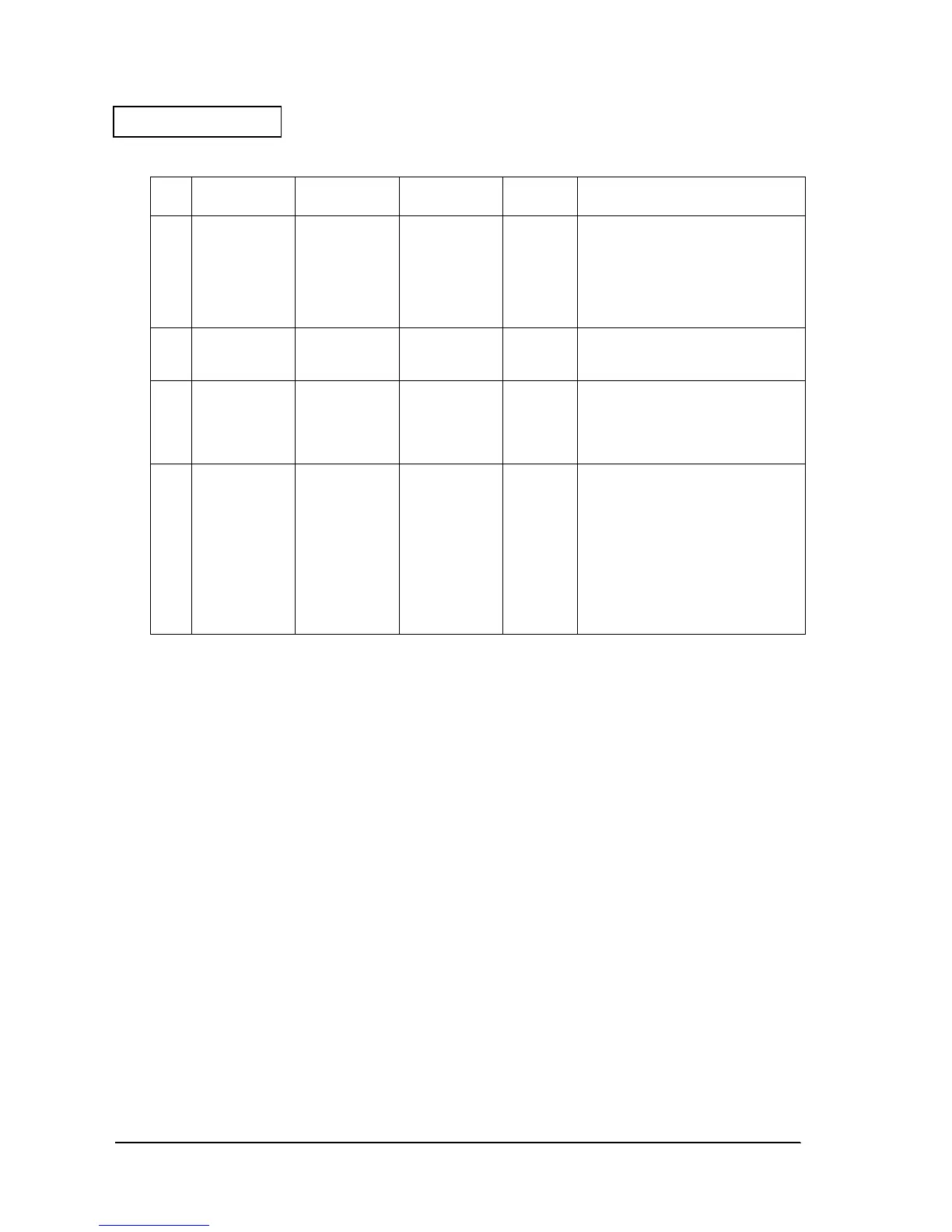
6 Logic voltage
(VCC_SEN)
CN30, pin 5
potential
Output only
when there is
output sensor
conductivity
when CPU
output port
(SEN_PWR) is "L."
5 V
±
5
%
The logic power supply circuit or Q44
could have malfunctioned.
7 Mechanism
voltage
(24VA)
Located near
Q17 drain
Output when
Q24 (C) is "0."
(24V SW2 = "H")
24 V
±
10
%
Q17 could have malfunctioned.
8 Mechanism
voltage
(24 VB)
Located near
Q7 drain
Only output
continuously
when power
supply unit is
connected.
24 V
±
10
%
TH1 could have malfunctioned.
9 Mechanism
voltage
(24C)
Located near
Q29 base
Output when
Q46 (C) is "0."
(24V SW1="H")
24 V
±
10
%
It is possible that the problem is pre-
arcing of the F2 fuse. The fuse may
have pre-arced because of a defect
in the 24V line circuit elements.
If pre-arcing of the F2 fuse happens,
do not repair the main circuit board
unit. The quality of several parts on the
circuit board is weakened by pre-
arcing of the F2 fuse, and safe
operation cannot be guaranteed.
Table1-3 Checking the power supply line
Step
# Type of Voltage
Location of
Measurement
Condition of
Measurement
Normal
Value Presumed Cause of the Error
 Loading...


