Rev. A Product Overview Appendix D-59
TM-H6000/H6000P Service Manual
Confidential
The drive signal to drive the phases is sent at the logical level of the PHASE1, 2 terminals. The
motor driver cannot operate unless signal 24VSW1 in the circuit diagram is set to HIGH
(controlled by the GA). When this signal is at a status other than HIGH, IC consumption is 0,
and no electricity goes to the motor.
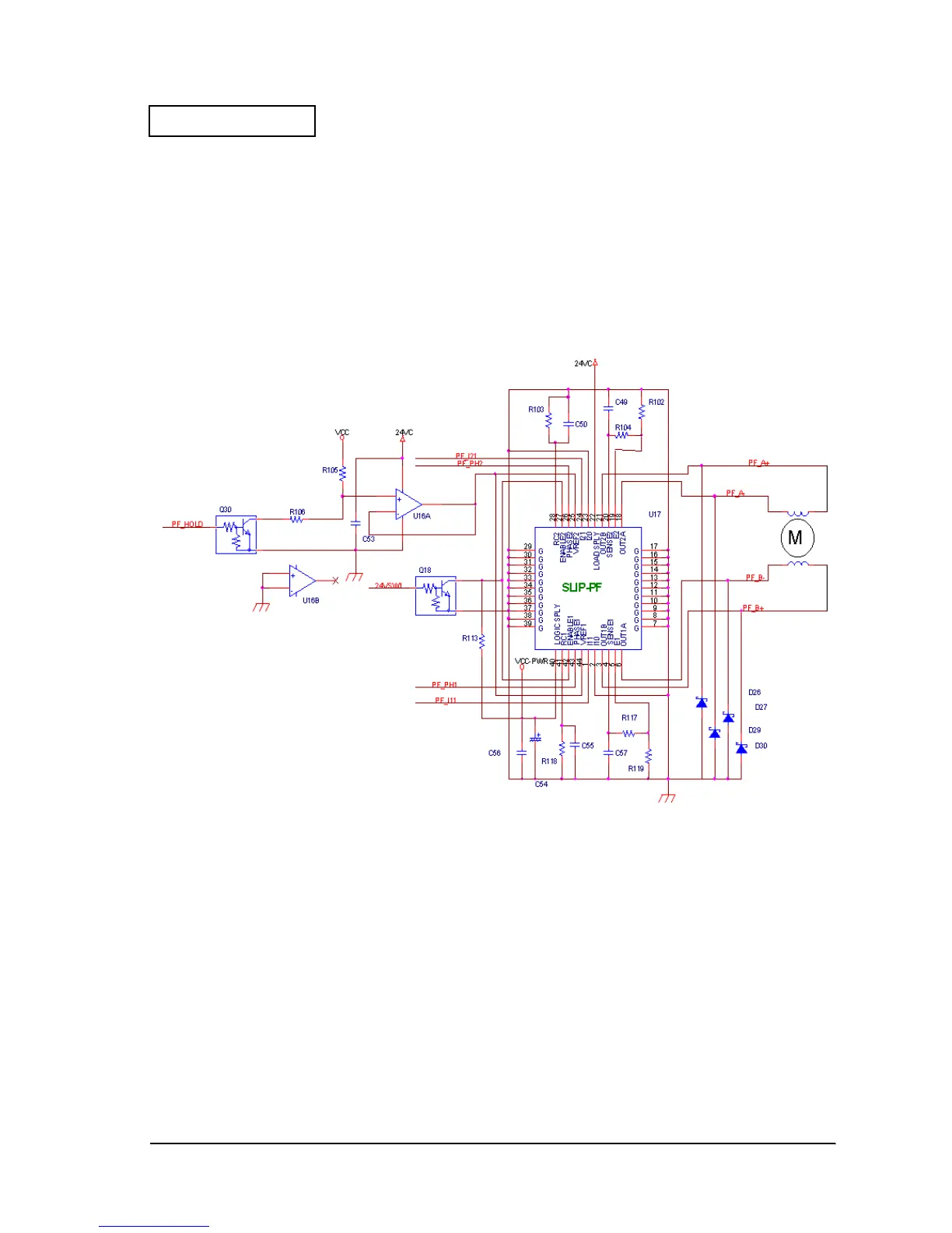
Slip Paper Feed Motor Drive Circuit
The slip paper feed motor is two-phase stepping motor. The driving method is 1-2 phase
excitation during acceleration and deceleration, and constant-current drive is performed with
2-2 phase excitation. Therefore, a dedicated constant-current drive chopping driver (U17,
A2917SEB made by Alegrow) is used.
Figure D-59
The circuit configuration is the same as the carriage motor driver, but the current setting is fixed,
and is changed between two levels by the output (PF_HOLD) of the GA (U30) port. The current
calculation procedure is described below.
Current = VREF/(10 ✕ Rs)
RS: 1Ω
VREF: VCC or voltage obtained by voltage division ratio of R105 and R106.
As for the carriage motor drive circuit, the driver IC is operated by setting the 24VSW1 signal
HIGH.
 Loading...


