Rev. A Product Overview Appendix D-61
TM-H6000/H6000P Service Manual
Confidential
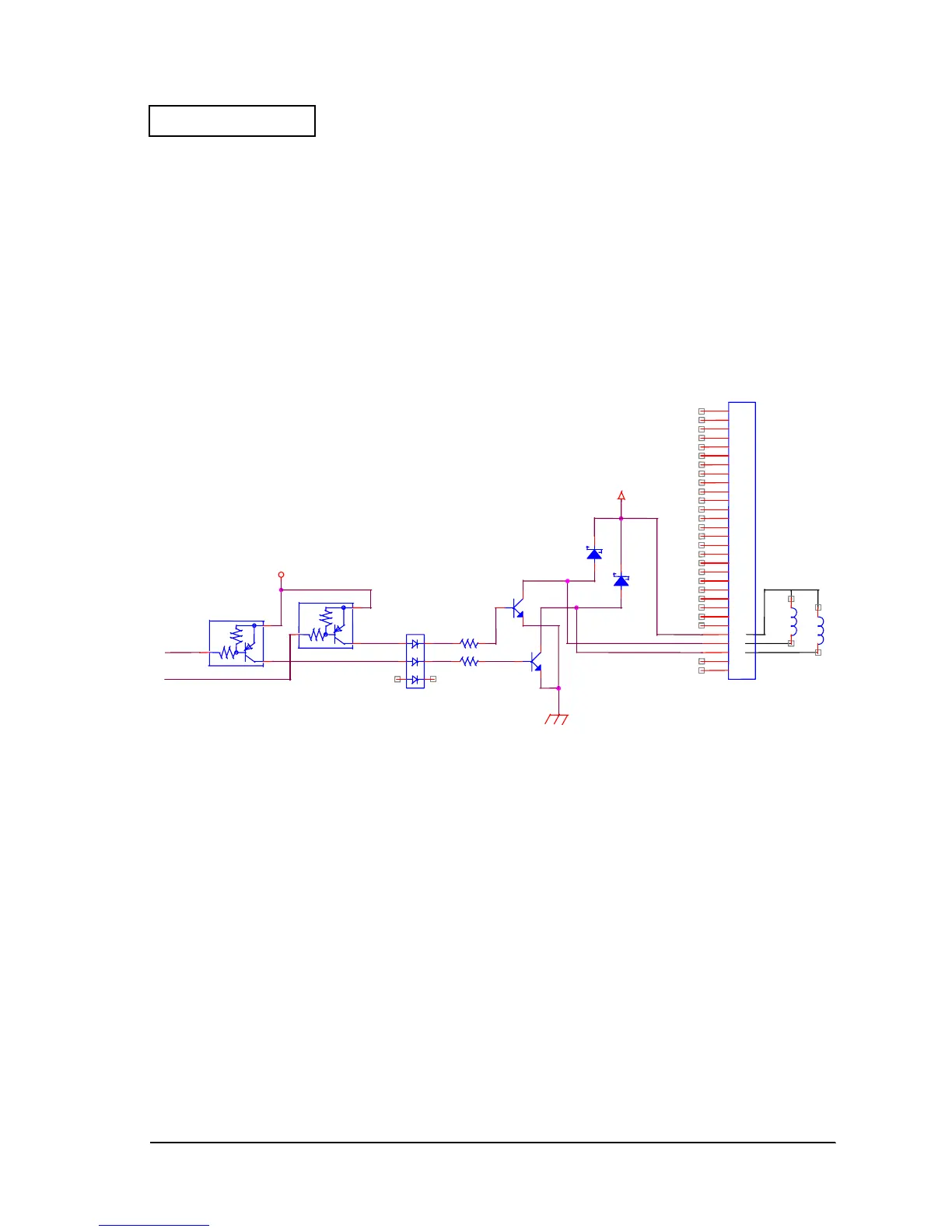
Lever Drive Circuit
This printer has two levers to drive the mechanism. The lever motor rotation enables lever A
and lever B to function. This controls the mechanism.
Lever A and lever B are solenoids driven by 24V. Simple drive of lever A and lever B is
performed by an NPN Darlington transistor. LEVER1 and LEVER2 are output signals from the
CPU.
• Lever A: Driven by a LOW level of the LEVER1 signal
• Lever B: Driven by a LOW level of the LEVER2 signal
Figure D-61
VCC
24VC
LEVER
LEVER1
LEVER2
LEVER-A
LEVER-B
CN30
1
2
3
4
5
6
7
8
9
10
11
12
13
14
15
16
17
18
19
20
21
22
23
24
25
26
27
28
29
30
Q43
Q54
R175
D17
R174
D44
Q42 Q53
D21
 Loading...


