3-10 Adjusting Rev. A
Confidential
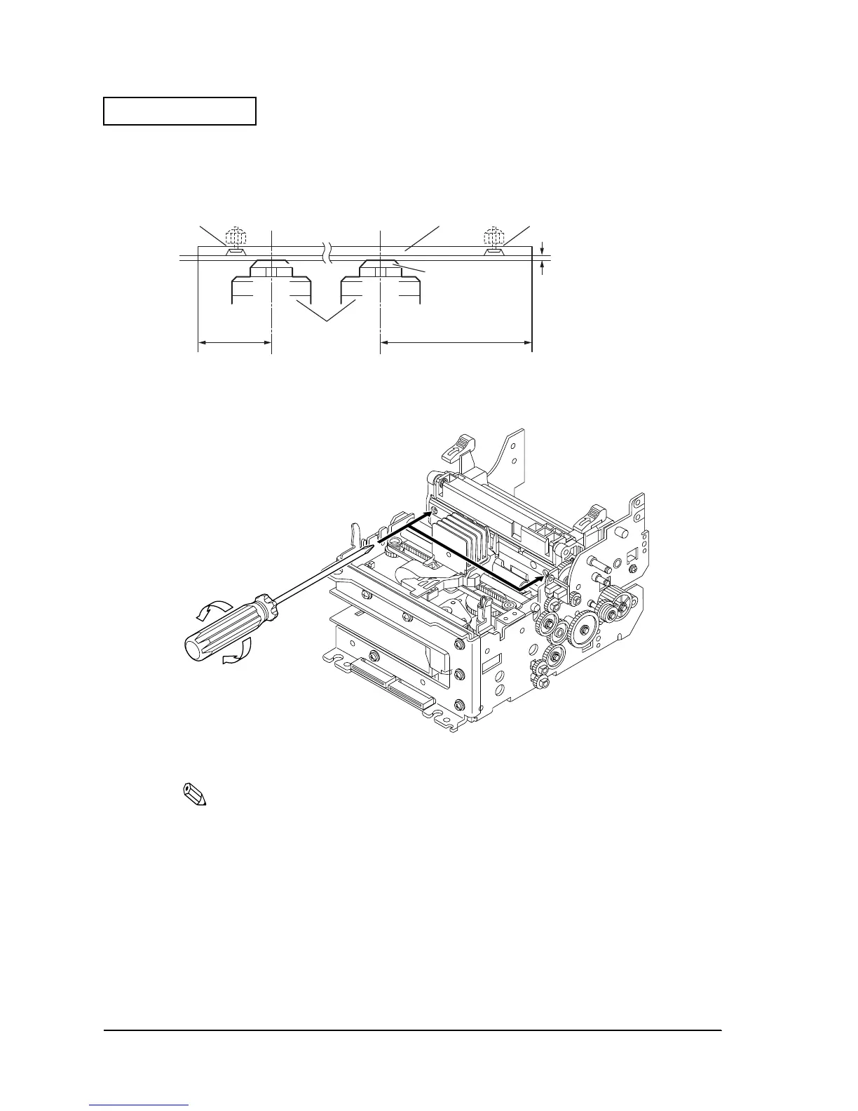
5. While using the thickness gauges, adjust the stopper screw of the platen set so that the
positions indicated below are 0.5 ± 0.05 mm.
The stopper screw of the platen set is located here.
Figure 3-9
Note:
The following shows the conditions for adjusting the platen gap to 0.5
±
0.05 mm.
❏ The 0.45 mm thickness gauge falls under its own weight.
❏ The 0.50 mm thickness gauge is pinched and will not fall between the platen and the print
head unit.
6. Attach the ribbon cassette cover and the carriage cover set frame.
20mm 40mm
0.5 +/- 0.05mm
Screw Platen set
Print Head
Screw
 Loading...


