55 / 144
8 • Measurement and adjustment
Art.-Nr.: 80116-271
04.06
Voltage
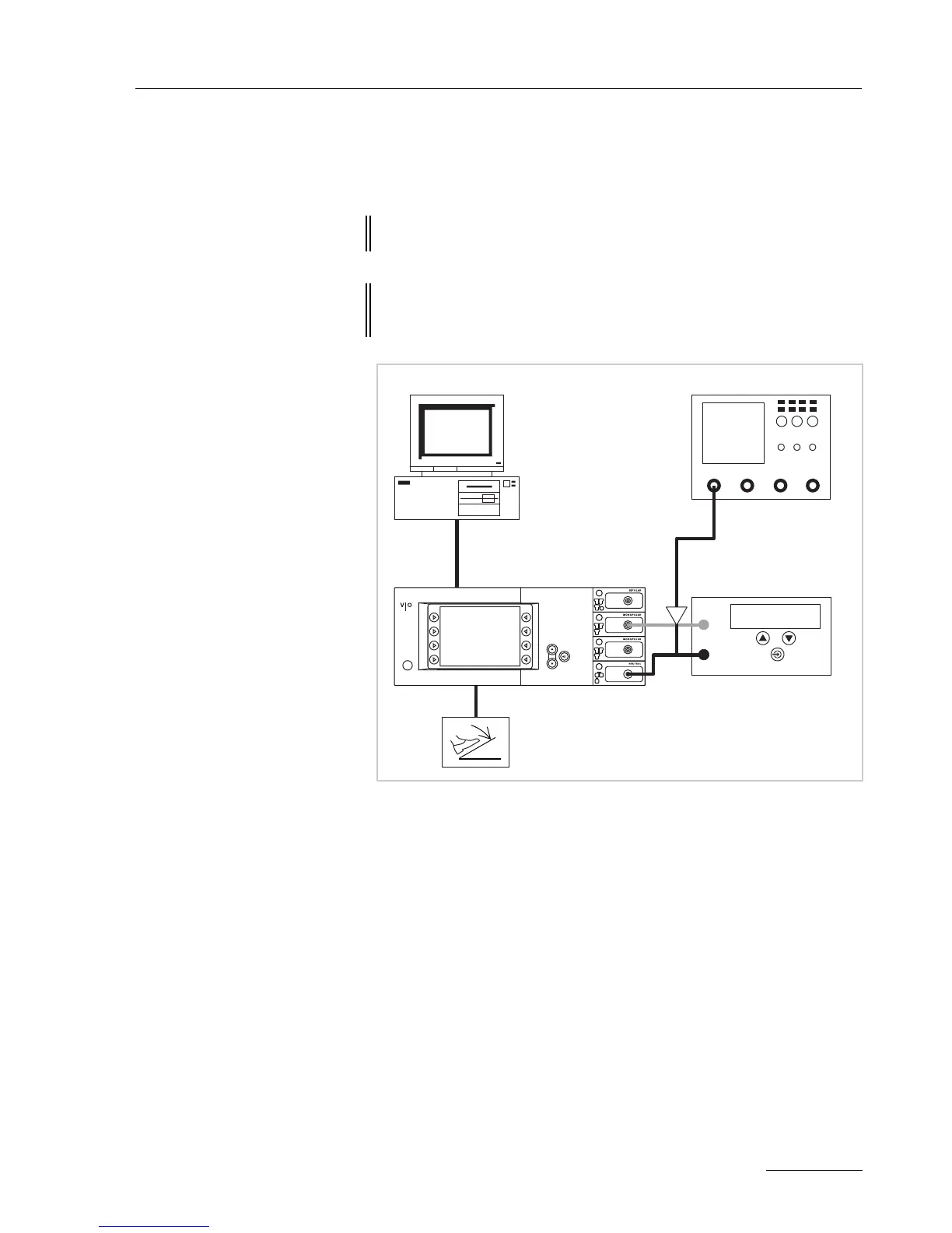
Test set-up
Fig. 8-3
• The test setup is designed as shown in the illustration above.
• The test specimen is connected to the power supply via the power
cord.
• The test specimen is switched on.
• On the PC the "VIO HF Adjustment Tool" software is installed.
Test procedure
1. Start "VIO HF Adjustment Tool" software.
2. Start the adjustment procedure with the <Start adjusment> but-
ton.
3. Perform adjustment steps 1 – 5 as described in the software.
4. Do not switch off the test specimen during rearrangement for
next test step.
ATTENTION! When connecting the probe to the input of the HF power meter,
make absolutely sure that minus is connected to the patient plate.
ATTENTION! For adjustment steps "Voltage range 700 V" and "Voltage range
3
kV" set the pulse duty factor on the probe to 1000:1 or else the
probe will be damaged.
ERBE
AE
NE
HF power meter
High Voltage
Differential probe
Desktop PC
ECB connection
Oscilloscope