57 / 144
8 • Measurement and adjustment
Art.-Nr.: 80116-271
04.06
Currents
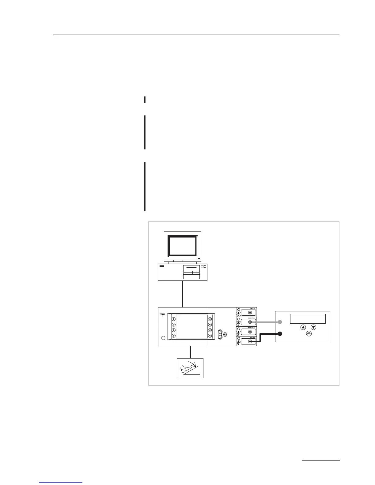
Test set-up
The currents are determined using a power meter.
Fig. 8-5
• The test setup is designed as shown in the illustration above.
• The test specimen is connected to the power supply via the power
cord.
• The test specimen is switched on.
• The test specimen is in normal operation.
• On the PC the "VIO HF Adjustment Tool" software is installed.
ATTENTION! No probe must be connected with the following measurements.
IMPORTANT! Only relevant for VIO 300 D from V 1.3.x onward
The SWIFT COAG ° mode should not be set. To ensure this, go to
SET-UP level 2 and if necessary switch the setting DRY
° /
SWIFT
° or from V 1.5.x onward SWIFT ° to OFF.
IMPORTANT! Only relevant for VIO 200 D
For the "current range 4 A" adjustment step call up the test pro-
gram "Enable Kali" (SET-UP level 2) and confirm with the Enter
button. HF prower limitation for SWIFT COAG can now be
increased to the 150
W for the adjustment step. When switching
off, the unit resets this increase again automatically.
ERBE
AE
NE
HF power meter
Desktop PC
ECB connection