10 • Maintenance and servicing
98 / 144
Art.-Nr.: 80116-271
04.06
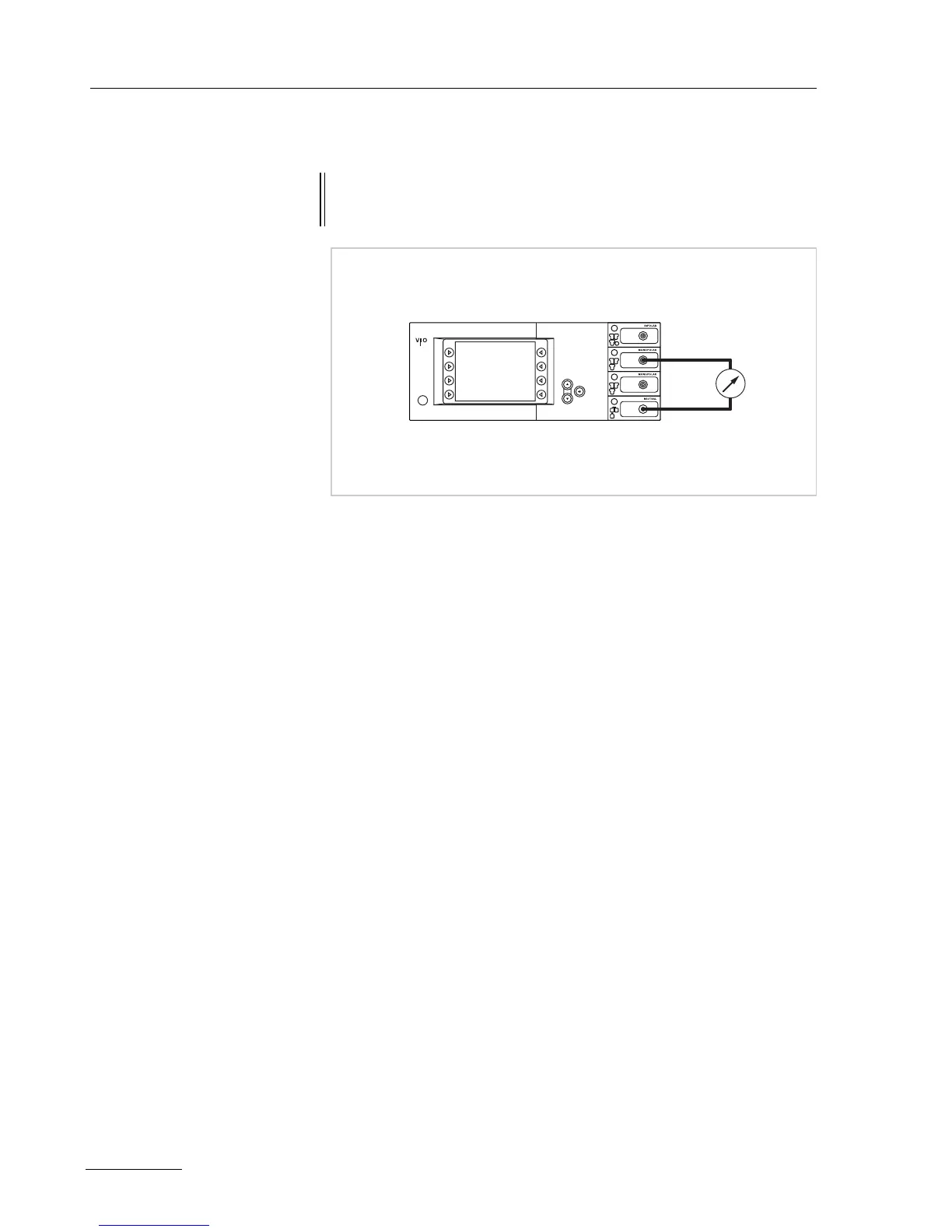
Test set-up
Fig. 10-1
• The test specimen is connected to the power supply via the power
cord.
• The NE receptacle of the test specimen is connected to the safety
tester via the patient cable with NE with the adapter cord.
• The AE receptacle of the test specimen is connected to the safety
tester via the patient cable with AE and electrode handle with the
laboratory cable.
Test procedure
1. Start safety tester in the "Insulation resistance" function The
measured value displayed should be >200
MOhm.
2. Start test specimen and select the test progam "TP relay".
3. In the test program "TP relay" use "All switch on" or "All" to switch
through all the output relays on the test specimen. When doing
so the measured value displayed on the safety tester must drop
significantly from >200
MOhm.
4. Determine insulation resistance using the safety tester. The
measured value must be >2
MOhm.
5. Document the measured value.
WARNING! Across the measuring lines there is the DC voltage of 500 V! In
order to avoid injuries, only switch on the test specimen and safety
tester when all the electrical connections have been made.
ERBE