SMART-2 Multi Functional Wireless Weighing Indicator User Manual
________________________________________________________________________________________________
Page 52
ANALOG OUTPUT mode selection
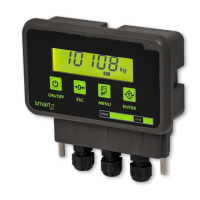
0-5V analog output connection
In the printed circuit of the indicator, the connections are as follows provided
that the leftmost terminal slot is number 1.
V
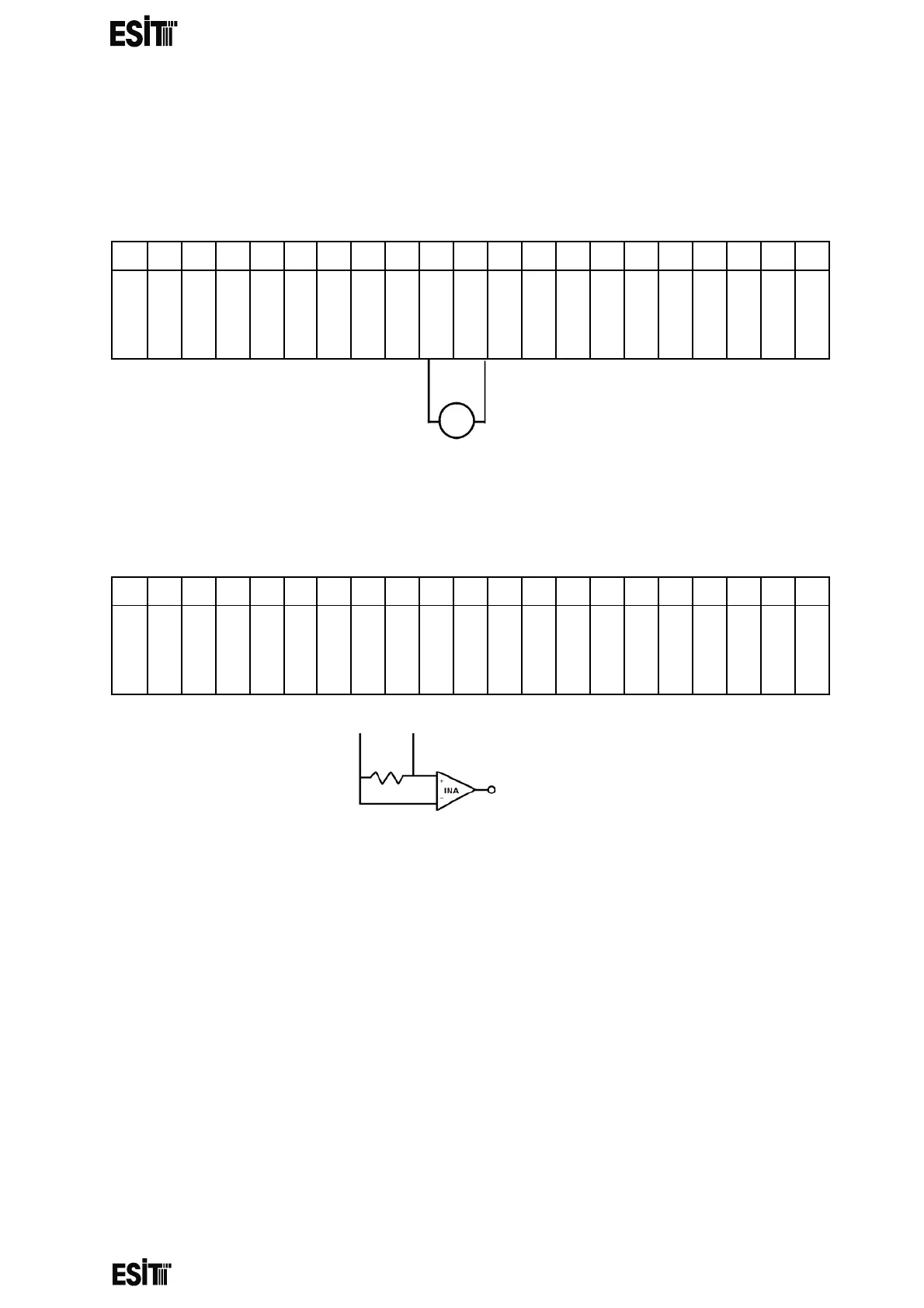
4-20mA analog output connection
In the printed circuit of the indicator, the connections are as follows provided
that the leftmost terminal slot is number 1.
WARNING: Changes to the card (short-circuit, open circuit and
interfering with components) other than those listed above may cause permanent
damage to the indicator and incorrect operation of the device and are not covered by the
warranty.