Ethos v1.5.7 and X18, X20 series User Manual
Outputs
The Outputs section is the interface between the setup "logic" and the real world with servos,
linkages and control surfaces as well as actuators and transducers. In the Mixes we have set
up what we want our different controls to do. This section allows these pure logical outputs to
be adapted to the mechanical characteristics of the model. This is where we configure
minimum and maximum throws, servo or channel reverse, and adjust the servo or channel
center point using the PPM center adjustment, or add an offset using subtrim. We can also
define a curve to correct any real world response issues. For example, a curve can be used to
ensure that left and right flaps track accurately. The various channels are outputs, for example
CH1 corresponds to servo plug #1 on your receiver (with the default protocol settings).
Although the radio is configured using percentages as input, servos and output devices are
controlled by a PWM (Pulse Width Modulation) signal in μs (microseconds). The relationship
between the units is as follows:
−150% = 732 μs
−100% = 988 μs
0% = 1500 μs
100% = 2012 μs
150% = 2268 μs
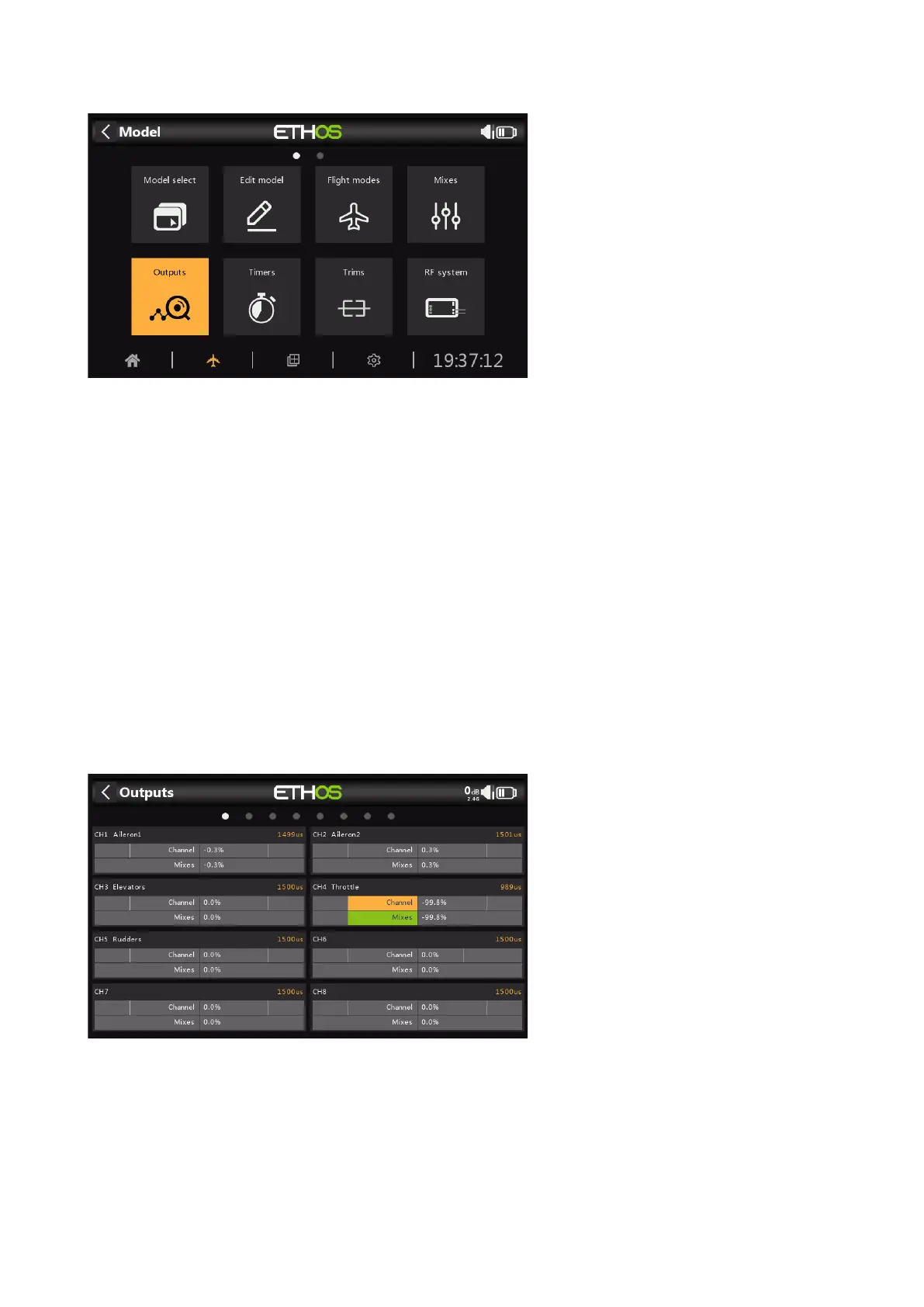
The Outputs screen shows two bar graphs for each channel. The lower (green) bar shows the
value of the mixes for the channel, while the upper (orange) bar shows the actual value (in
both % and µS terms) of the Output after the Outputs processing, which is what is sent to the
receiver. In the example above you can see that both the mixes and output values for CH4
Throttle are at 100%.
The channels that are not being output to the RF module are shown with a darker background.
In the example above, all eight channels are being transmitted, so they have a lighter grey
background.
 Loading...