MAINTENANCE MANUAL
Effectivity: All
Page 24-41
Edition 2 | Rev. 1
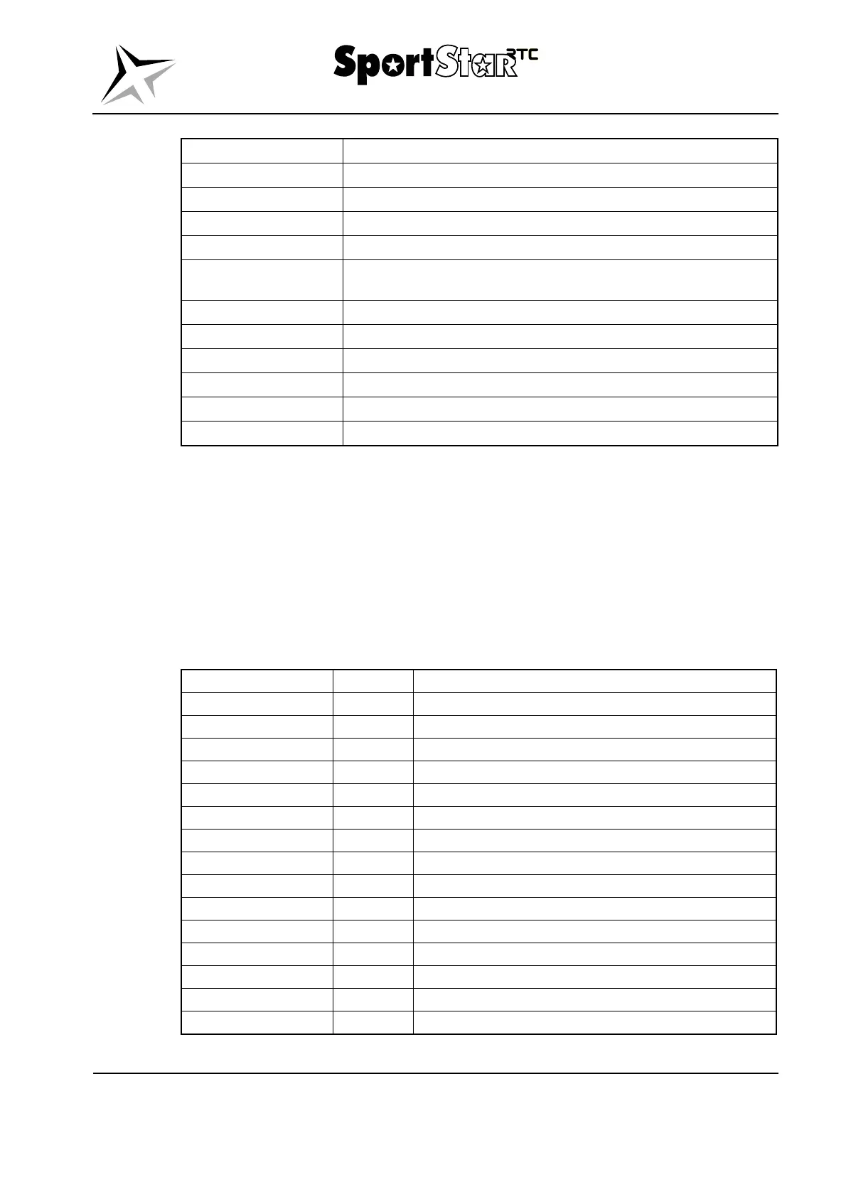
Designation Description
MASTER SWITCH
Switches on / off the electrical network
GEN
Switches on / off the generator
AUX. GEN
Switches on / off the auxiliary generator
AVIONICS SWITCH
Switches on / off avionics power supply
BATTERY G3X
Switches on / off the power supply of all devices connected to the
backup battery
Switches on / off the strobe lights
POS. LIGHTS
Switches on / off the position lights
LDG LIGHT
Switches on / off the landing light
Switches on / off the electrical fuel pump
Switches on / off the intercom
SOCKET
Switches on / off the 12 V socket power supply
Table 24-4 Switches – Garmin G3X system, typical layout (from the right)
B. Circuit breakers
The circuit breakers protect the individual electrical circuits from overloading and they are
located in two blocks on the left side and on the right side below the instrument panel. The
circuit breakers are permanently switched on.
The sequence of the circuit breakers in the tables shows the typical installation of the circuit
breakers for the airplanes equipped with analog instruments and for the airplanes equipped with
the Dynon SkyView system. The optional equipment isn´t included. The Pilot´s Operating
Handbook for SportStar RTC airplane shows the layout of circuit breakers corresponding to
particular airplane.
Designation Value (A) Description
Circuit breaker of battery
1 Circuit breaker of clock
GEN
25 Circuit breaker of generator
TURN IND.
2 Circuit breaker of turn indicator
3 Circuit breaker of attitude horizon
3 Circuit breaker of directional gyro
Circuit breaker of strobe lights
2 Circuit breaker of position lights
4 Circuit breaker of landing light
Circuit breaker of electrical fuel pump
1 Circuit breaker of signalization
1 Circuit breaker of pitch trim
Not used - -
Not used - -
1 Circuit breaker of stall warning system
Table 24-5 Left panel of circuit breakers – analog instruments, typical layout (from the right)