3
4
746 C - 844 C 12 532150 - Rev.A
13
17
12
19
14 15
5
4
2
8
9
7
10
11
3
1
6
18
16
Translation of the original instructions
ENGLISH
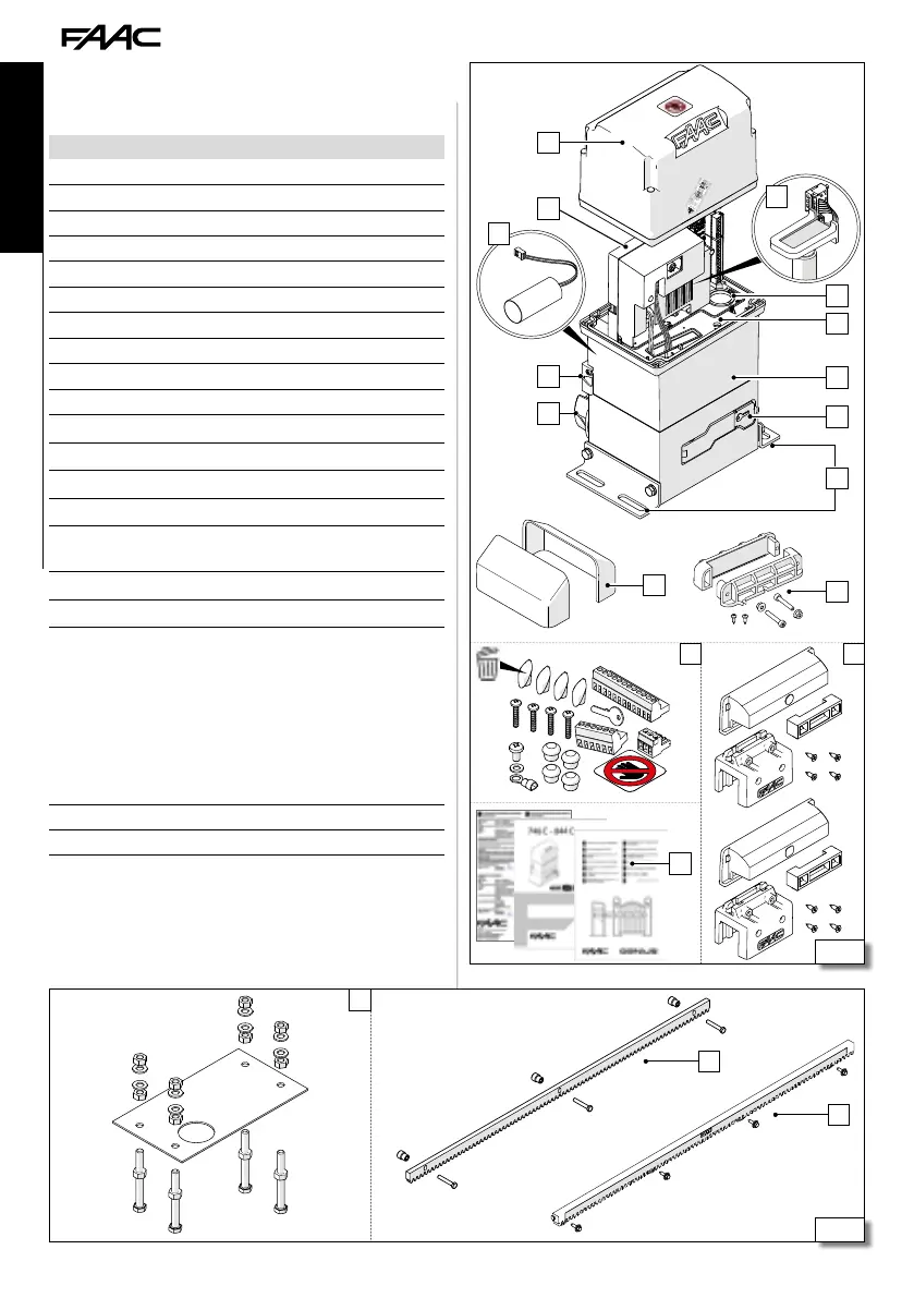
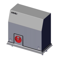
2.9 COMPONENT IDENTIFICATION
COMPONENTS SUPPLIED
Gearmotor
1 Casing
2 Electronic board E781 with protective cover
3 Thrust capacitor (inside the half-body)
4 Limit switch sensor
5 Pinion (Z16/Z20 Module 4) with hand guard
6 Encoder
7 Oil filler plug
8 Earth connector
9 Gearmotor body
10 Release lever with key
11 Mounting brackets
Hardware/accessories
12 Gearmotor bracket guards
13 Cable glands to install in the cable compartment
14
Screws and screw covers for the cover, terminal boards, cable lug
for earth cable and adhesive hazard warning sign, release key
15 Closing and opening magnetic limit switches
16 Supplied documentation (hard copy and online)
COMPONENTS SUPPLIED SEPARATELY
The installation requires the following components
FAAC.
17
18
Nylon rack with mounting hardware (for leaves weighing up to
400 kg max) and Self-tapping screw kit/Steel rack with spacers
(for leaves weighing more than 400 kg)
19 Foundation plate with mounting hardware
DANGER, AUTOMATIC MOVEMENT warning sign