KT5500 5-
1
/
2
” Tong & CLInCHER® BaCKup
SECTIon ConTEnTS
7.10
TECHnICaL ManuaL
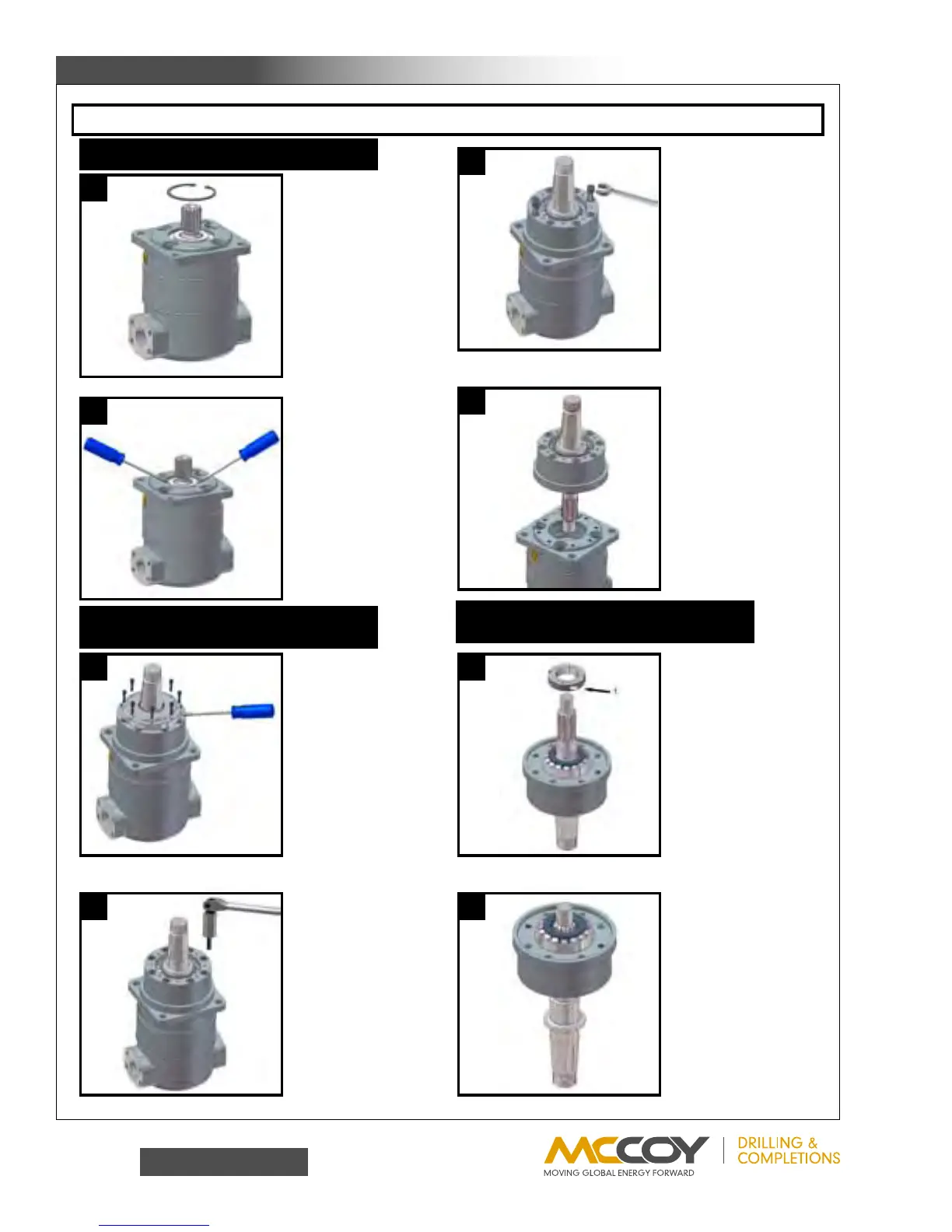
HyDRauLIC MoToR InfoRMaTIon
WARNING: RINEER RECOMMENDS FOLLOWING ALL STANDARD SHOP SAFETY PRACTICES SPECIFICALLY INCLUDING WEARING OF EYE PROTECTION.
1
2
3
4
5
6
7
8
1) Remove snap ring
WARNING: Use caution
when removing snap ring.
If released accidentally it
can become an airborne
hazard.
1) Pry out shaft seal plate
with two screw drivers.
2) Remove seal plate o-
ring from groove in bearing
bore.
1) Loosen and remove 8
each 10-32 bolts.
2) Pry off seal plate with
screw driver.
Loosen and remove 8
each 3/8" bolts with 5/16"
socket head wrench.
1) Press shaft out of
bearing box.
2
) Proceed to step 9,
disregarding steps 11 & 12
1) Loosen clamp screw in
lock nut.
2) Unscrew lock nut and
remove.
Lift up on the bearing box
to remove from motor.
1) Two of the 3/8" bolt
holes are provided with
jack screw threads.
2) Insert a piece of 1/4"
round stock by 2-1/2" long
into each jack screw hole
3) Screw two 7/16-14 bolts
into the jack screw threads
until the bearing box is free
o
f the motor.
REMOVAL OF SHAFT SEAL
REMOVAL OF WHEEL MOTOR SEAL
PLATE AND BEARING BOX
DISASSEMBLY OF WHEEL MOTOR
BEARING BOX