KT5500 5-
1
/
2
” Tong & CLInCHER® BaCKup
SECTIon ConTEnTS
7.14
TECHnICaL ManuaL
HyDRauLIC MoToR InfoRMaTIon
WARNING: RINEER RECOMMENDS FOLLOWING ALL STANDARD SHOP SAFETY PRACTICES SPECIFICALLY INCLUDING WEARING OF EYE PROTECTION.
33
34
35
36
B
A
9
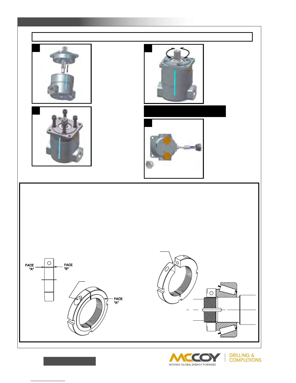
1) Install dowel pins into
rotor/stator cartridge.
2) Pour a small amount of
clean oil into the cartridge.
3) Install front housing onto
rotor/stator cartridge.
4) Make sure alignment
marks are lined up.
1) Install 5/8-11 bolts.
2) Torque bolts to 50 ft./lbs.
1) Rotate shaft in both
directions to assure that the
shaft turns smoothly.
2) Torque motor to 190 ft./lbs.
3) Rotate shaft again in both
direc
tions to assure that the
s
haft turns smoothly.
NOTE: Spool should be
oriented as shown for two
speed motors with model
codes 62, 63, 68, & 69.
NOTE: Slight design
variations may exist in
motors manufactured
either before or after the
printing of this manual.
SPOOL ASSEMBLY FOR THE
TWO SPEED MOTOR
1)� Clean ALL assembly parts w/ lacquer thinner.
2)� Dip clampnut and clamping bolt separately in lacquer thinner.
� (Steps 3 thru 10 must be conducted to completion ONE assembly at a time.)
3)� Press bearing cups into bearing housing. Make sure they are pressed completely against bearing shoulders.
4)� Coat inner race of large cone with #609 (green) Loctite and press cone onto the shaft. Make sure the cone is completely against the shoulder of the shaft.
5
)� Insert shaft and large cone into bearing housing.
6)� Coat inner race of small cone with #609 (green) Loctite and press small cone onto shaft.
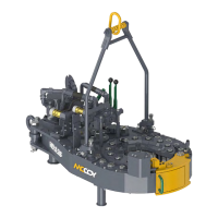
7)� Apply #272 (red) Loctite to the clampnut threads of the shaft. Apply #242 (blue) Loctite to the threads of the clamping bolt and install in the clampnut.
8)� Spin clampnut onto shaft with the "B" face towards bearings. After the nut threads are fully engaged, but prior to the nut contacting the bearings, �
� tighten the clamping bolt until there is drag on the clamping nut (see note Fig. 1). Tighten the nut until a 20 to 30 inch pound rolling torque is achieved.
9)� Tighten clamping bolt on clampnut to 70 inch pounds and recheck rolling torque. Apply inspectors lacquer to head of the bolt.
10)� Allow a minimum of 24 hrs. to dry.
Figure 1
CUTAWAY
Note:
The slit in the clampnut
allows for loose
assembly on the shaft.
Once in position, the
clampnut clamping bolt
MUST be tightened to
a slight drag in order to
correctly engage the
threads on the shaft to
achieve the clamp
force required.
CLAMPING BOLT
WHEEL MOTOR SHAFT AND BEARING ASSEMBLY PROCEDURE