KT5500 5-
1
/
2
” Tong & CLInCHER® BaCKup
SECTIon ConTEnTS
2.8
TECHnICaL ManuaL
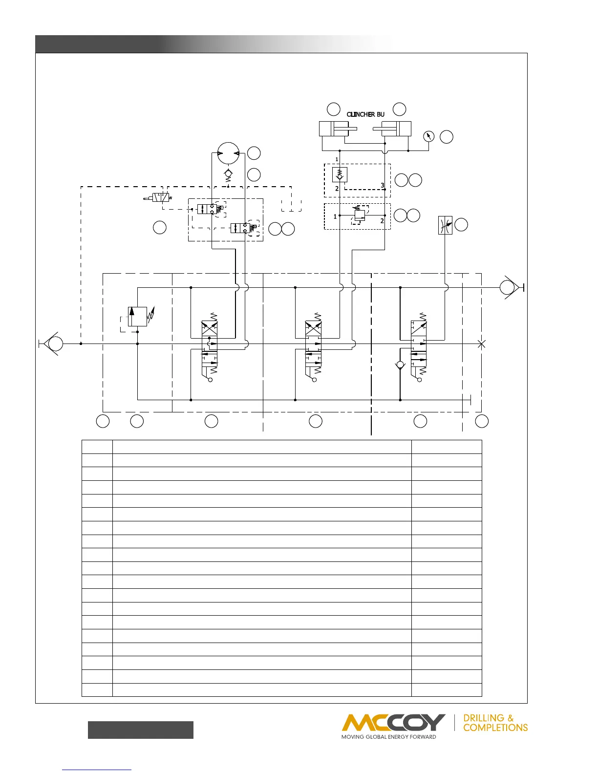
C. HYDRAULIC SCHEMATIC / COMPONENT IDENTIFICATION
Your tong may be equipped with one or two control valves, as well as safety door switch and hydraulics, depending upon
the specific model. Disregard the control valves indicated on the following schematics that do not apply to your model.
Item Description Part Number
1 InletValveDVA35-A880w/2500TO3500DVG35HMRVCARTRIDGE 10-9016
2 ReliefValve,DVA35-MRV-1 10-0010R
3 MotorSection,DVA35-MA8,4WAYSAEPORTS 10 - 9014
4 BackupSection,DVA35-DA84WAYSAEPORTS 10-9019
5 LiftSection,DVA-SA8,1”ORBPORT 10-9015
6 OutletSection,DVA35-TR99,SAEPORT 10-0086
7 FlowControlValve,N800S(notshown) 08-9062
8 Pilot-To-OperateCartridgeValve,LKHC-XDN 08-1625
9 SafetyDoorValveBlock 101-0727
10 SafetyDoorSwitch 08-0337
11 CheckValve,SH4600 87- 0110
12 RineerGA15-13HydraulicMotor 02-9022
13 ReliefValve,RPGC-KAN 08 -1180
14 ReliefValveBlock,SunCAJ 08-1844
15 CheckValve,CKEB-XCN 08-0481
16 CheckValveBlock,SunBCJ 08-1327
17 3000psiPressureGauge 02-0245
18 CLINCHER®BackupCylinder 1403-00-00B
SETup & opERaTIon
P
T
M OTOR
LIFT
14 13
16 15
17
18 18
1 2 3 4 5 6
12
11
9 8
10
7
OPTIONAL
OPTIONAL
OPTIONAL