KT5500 5-
1
/
2
” Tong & CLInCHER® BaCKup
SECTIon ConTEnTS
2.19
TECHnICaL ManuaL
SETup & opERaTIon
Compression Load Cell Configuration (continued):
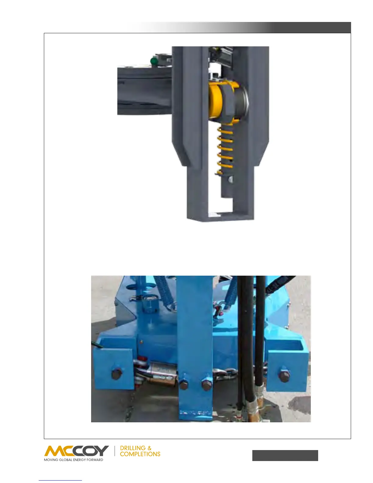
4. Tension Load Cell Configuration
Thebackupiscoupledtotherearlegoftheassemblywithatensionloadcellononeside,andarestraintchainontheother.
To change the torque measurementconfiguration (make upto break outor visa versa) simply remove the heavy duty bolts
securingtheloadcellandrestraintchains,andswitchtotheoppositesides.Reinstalltheheavydutyboltstosecuretheload
cellandrestraintchainsinplace.Foryourreferencetheassemblyinthefollowingillustrationhasbeenconfiguredtomeasure
makeuptorque.Ifmeasurementofbreakouttorqueisdesiredtheloadcellwouldbeconnectedbetweentherighthandside
oftherearlegandthebackup.
Load cell configured for
break-out operations