3. Electrical installation
3−15
Festo P.BE−CPX−CMAX−SYS−EN en 0908NH
Basic information on the power supply concept of the
CPX terminal can be found in the CPX system description.
A few examples can be found in Fig.3/1, Fig.3/2 and
Fig.3/3.
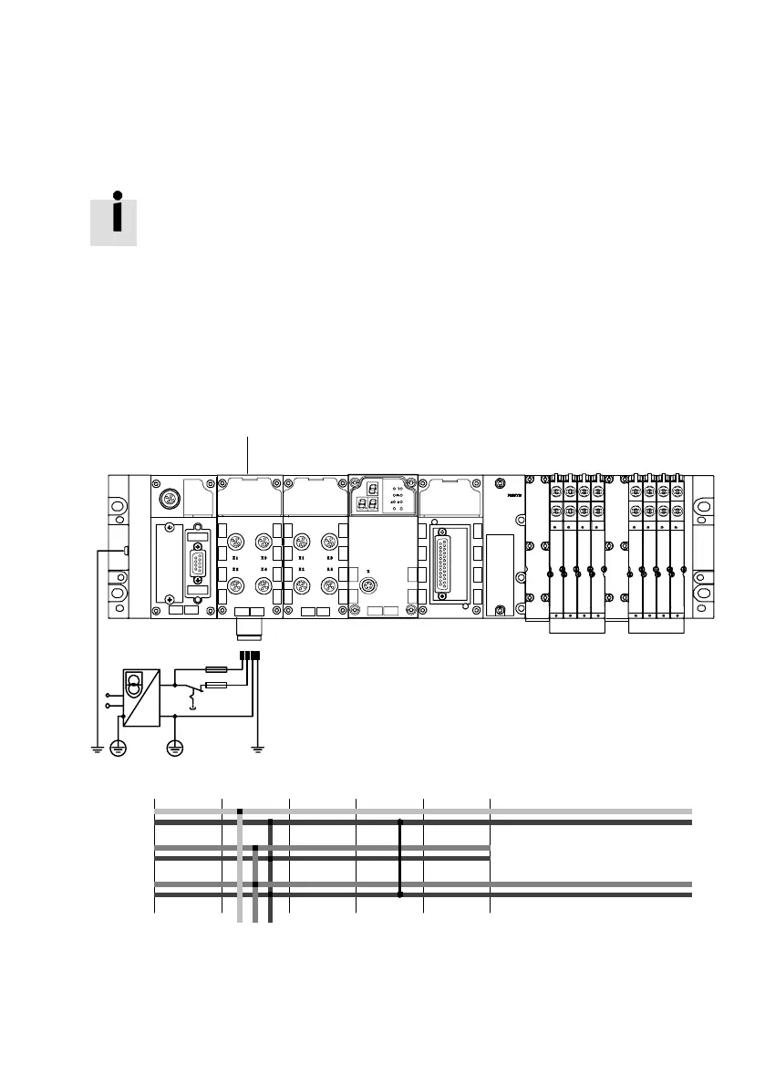
A central (shared) power supply (Fig.3/1)
In the example, the entire CPX terminal and the CMAX
positioning system are provided with power via the system
supply.
24V
VAL
0V
VAL
24V
OUT
0V
OUT
0V
EL/SEN
1
1 2 34
Schematic representation:
8DI
8DI4DO
CMAX
8 A8 A
MPA
24V
EL/SEN
1 Interlinking block with system supply (supplies the CMA X and the MPA
pneumatics)
Fig.3/1: Common power supply (example)

 Loading...