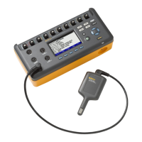
Vital Signs Simulator
Instrument Familiarization
7
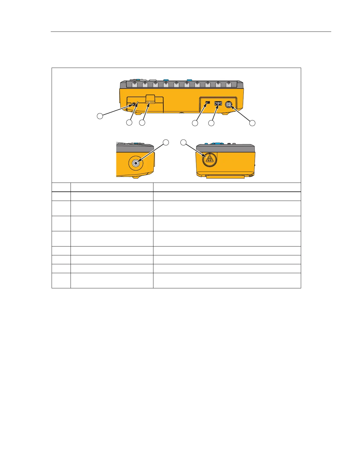
Table 6 is a list of controls on the back, front, and side of the Product.
Table 6. Back, Front, and Side-Panel Connections
Front
Right
Back
1
4
7 8
5 6
2
3
lh035.e
s
Item Name Description
AC/DC Supply Connector Input jack for the DC output of the AC/DC supply connector.
Battery Charge LED
Battery charges when LED shows red. Green shows battery
charge is complete.
Battery Latch
Locks the battery pack into the Product. Push down to remove
the battery pack.
Mini B USB Device Port
Used to connect to a PC for remote control or download test
results data to a PC.
USB A Controller Port For external keyboard, barcode reader, or printer.
ECG BNC Connector High-level output of ECG signal.
Air Port Connector Pressure port for NIBP cuff and monitor.
Magnetic Holder for SpO
2
Finger
Module
Holds the SpO
2
Optical Emitter and Detector finger module in
two orientations.