5.2.1 Goto a Waypoint
In the example, the direction to the waypoint is northeast,
ground speed, the distance to the waypoint and the calculated
arrival height over the waypoint (Alt a WP) are displayed in the
user-fields. The user-field Alt a WP is the height above the
optimum glide slope to the waypoint. The data field will invert
(white numbers on a black background) when Alt a WP
becomes positive. The calculated arrival height assumes that
there is neither lift nor sink along the flight path and that the
wind remains constant. For more information please refer to
Section 5.4.4, Final Glide.
You can also see A BG WP in the example, which is the pilot’s
altitude above or below the best glide line to the next waypoint
(or goal if on final glide). When A BG WP displays 0, the pilot
has sufficient altitude to just be able to reach the waypoint/goal
by flying at the best glide speed. The data field will invert (white
numbers on a black background) when A BG WP becomes
positive.
When thermaling you should climb until Alt a WP shows zero,
which means you can go on glide at McCready optimum speed
to fly. A BG WP then shows how much height you will have
above the best glide slope to use while gliding to goal.
Generally you should not proceed to goal if the A BG WP
shows zero or negative numbers – reaching goal would be impossible without encountering lift on the way.
The user-field A BG Goal displays your altitude above (or below) best glide path to goal around the remaining
turnpoints. This value takes the calculated or the manually entered wind into account for each leg of the course.
This feature is particularly useful when you have gained sufficient altitude to make it around the last turnpoint (or
last few turnpoints in a tight course) and make goal. However, it is not possible for the 6030 to anticipate a
change in the wind speed or direction along the course that will affect the accuracy of this value.
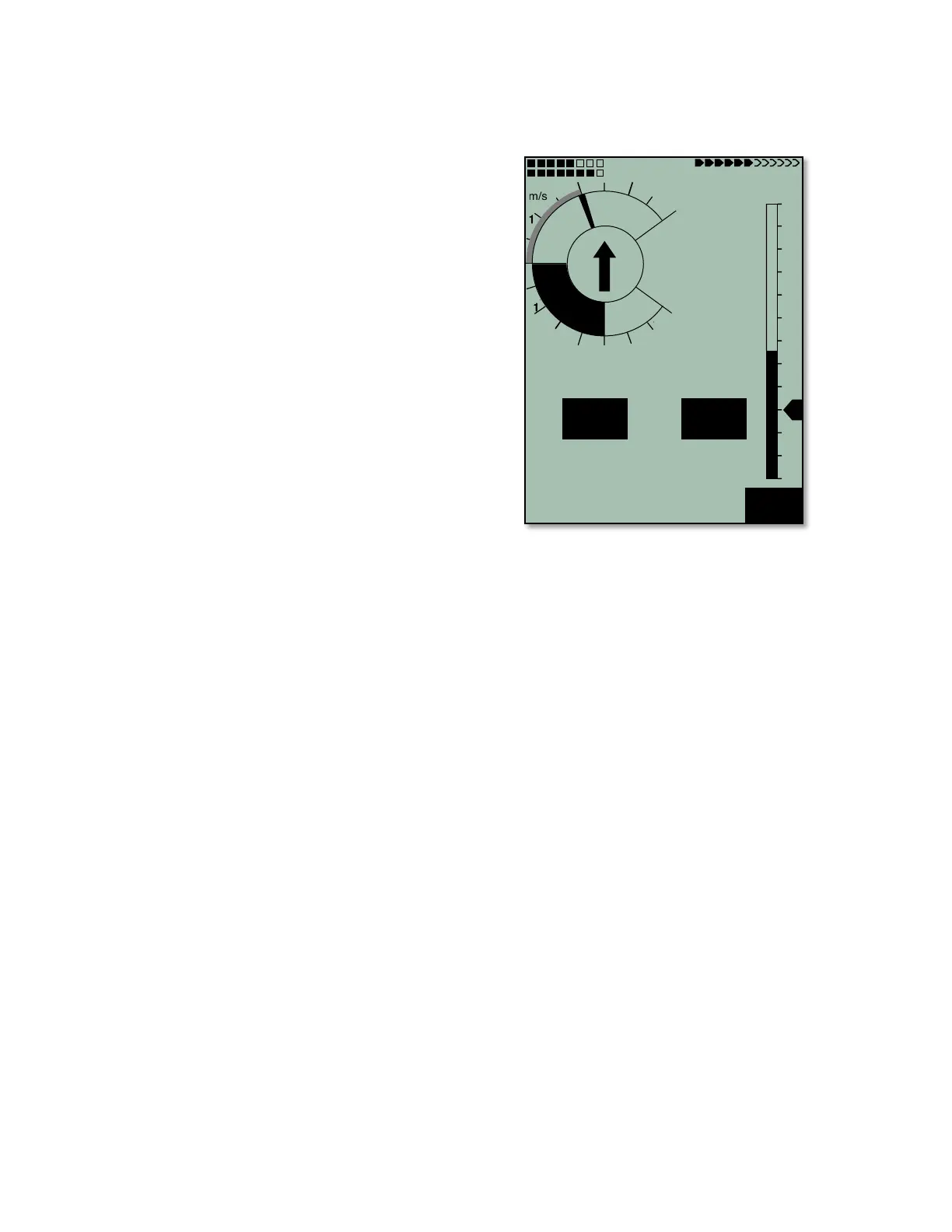
5.2.2 Correct Bearing in a Cross Wind
If you encounter a strong cross wind on the way to a waypoint/goal, you can find the optimal angle between
your destination and the wind by gradually changing your direction of flight against the wind until the directional
pointer in the center of the compass rose points directly upwards, as shown in the example above. By doing this
you can be sure that your flight path over ground is a straight line to goal (i.e., track=bearing) and consequently
the shortest one – and you will avoid the well-known “pursuit curve.”
5.2.3 Wind Component
When flying to a waypoint – and, even more importantly, to a goal – the wind component (the difference
between ground speed and air speed over the track) is very important. In most cases the wind does not blow
directly from the front or from behind, but from the side. If the wind component displayed in the user-field Wind
Comp is positive, then you will fly with a tail wind, and the glide ratio over the ground will improve. If it is
negative, the glide ratio will worsen. To find the correct angle between the destination and the wind when a
strong cross wind is present, please refer to Section 5.2.2.
The 6030 takes the wind component into consideration when calculating the optimum speed to fly, and with final
glide calculations. The wind component can be either automatically entered or manually entered by the pilot.
Manual entry of the wind component may be preferable to automatic in some circumstances. Some examples
are:
• There is a significant velocity and/or directional wind shear
• The calculated wind speed is underestimated due to “blocking” when climbing in a strong thermal. The true
wind in this case can be stronger than the automatic calculation.
• On glide, small wind fluctuations can cause differences of the calculated arrival altitude (these can also be
caused by yawing). A manual wind component will keep the result more stable.
• When a more conservative approach to goal in a headwind is desired.