3.5.3 Polars
In order to receive accurate speed to fly, netto vario and glide ratio information from the 6030, you must enter an
accurate polar for your flight configuration (i.e., your particular glider, wing loading, harness, air speed sensor,
etc.). You can obtain the polar for your glider from your glider’s manufacturer and then, by trial and error, adjust
those values to match your actual performance. A more accurate method is to use the 6030 to record the data
to build your polar by flying data recording flights in smooth air. During the flight, each air speed between V
stall
and V
ne
should be maintained for several seconds. With the aid of FlyChart 4.52.21 or later, the data attained
can be used to generate your own actual polar curve.
Once the polar has been developed, only two polar curve points need to be entered into the 6030: the speed
(mph or km/h) and corresponding sink rate (ft/min or m/sec) for (1) minimum sink and (2) a speed in the upper
range of your glider (best maneuvering speed). These two air speed/sink rate pairs are entered manually into
the 6030 in Menu>Pilot settings>Polar data. You may notice that the polar values you enter are rounded- this is
normal and is no cause for concern. In addition to the two sink-rate/air-speed pairs, you must also enter the
average altitude at which you flew when conducting the testing, using the altitude field of the Polar data menu.
All of the documented polar curve points will be converted and saved as “Indicated,” and the polar curve will
now be valid for all altitudes.
The 6030 can store the polar data for two different gliders so that you do not need to re-enter the polar data
pairs when flying your second glider. To enter and use a second polar data set, change the use set field in
Menu>Pilot settings>Polar data to either 1 or 2.
3.6 Audio
The volume for the 6030 audio is adjusted with the & key. Short press the & key to scroll through the volume
settings. The sound levels are: 0% – 25% – 50% – 75% – 100% and are momentarily displayed in the
Information Field when a change in volume is made. All of the sounds described in this section can be heard in
Simulation mode.
Automatic Volume Control: The basic sound levels of 25%, 50%, and 75% will slowly increase automatically
when the air speed exceeds 25 mph (40 km/h), but never to greater than 100%.
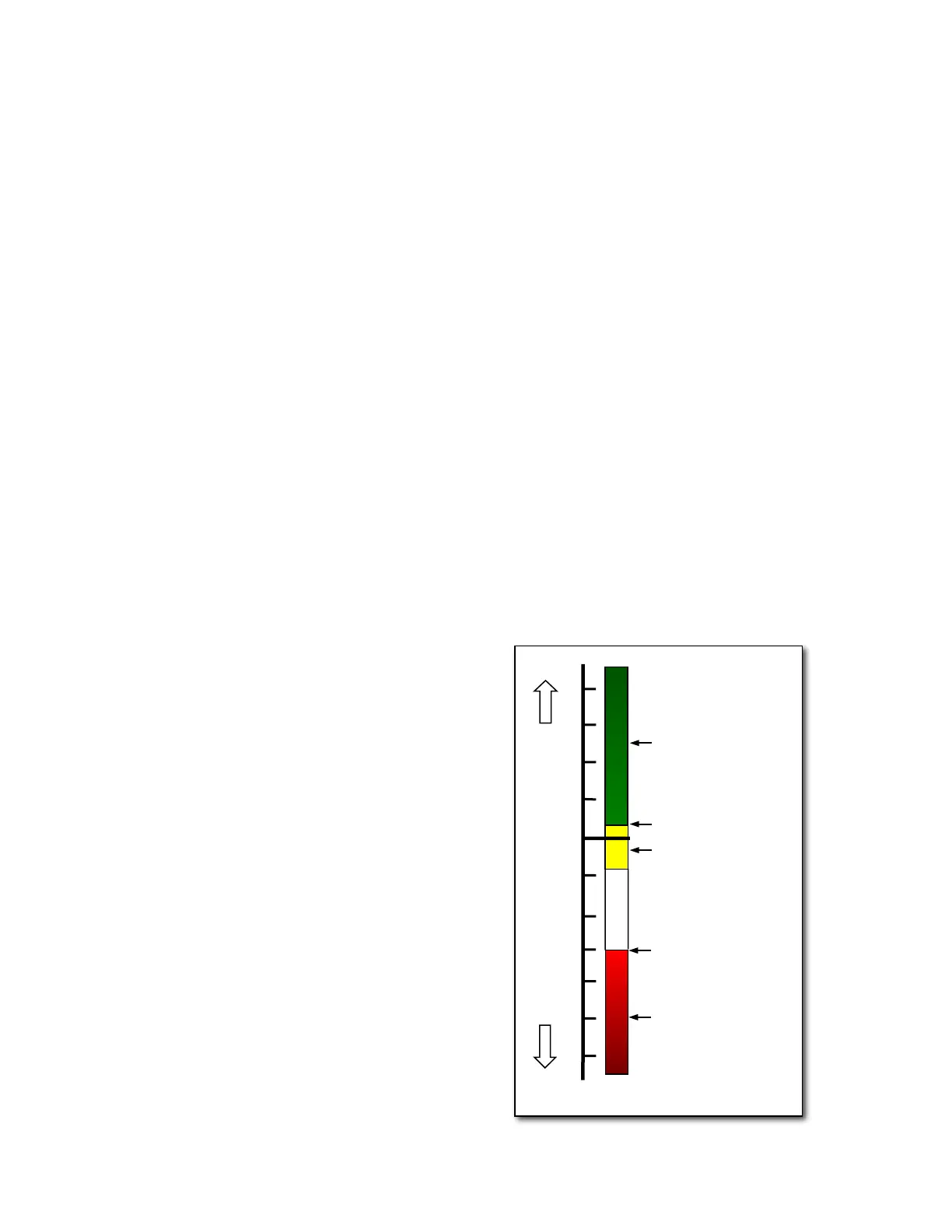
Ascent Tone: The ascent tone starts when the climb rate
exceeds a predetermined threshold. The ascent tone
threshold is the lift value that must be exceeded to start the
ascent tone (beeping). If the vario units have been set to
ft/min, the default threshold is approximately 4 ft/min and can
be altered to between 0 and 39 ft/min. If the vario units have
been set to m/sec the default is .02 m/sec and can be set
between 0 and 0.2 m/sec. The value can be changed in
Menu>Pilot settings>Acoustic vario>Lift audio threshold. The
greater the threshold value, the greater the ascent rate
needed to initiate the ascent tone. As stronger lift is
encountered, the frequency (tone) and tempo of the ascent
tone will increase at a predetermined rate (see Modulation
and Pitch below). It is possible to set the start frequency of
the ascent tone between 600 and 1400 Hz in the ascentF field
in Menu>Pilot settings> Acoustic vario>Customize sound.
Nascent (Near) Thermal Tone: This is a beep tone similar to
the ascent audio that indicates lift that is not quite strong
enough to trigger the ascent tone but may deserve
investigation when finding a source of lift is critical. The
nascent thermal tone is only active in flight to prevent
unnecessary and distracting beeping while standing at launch
waiting to takeoff or after landing. The upper threshold of this
tone is the same as ascent tone threshold and the lower limit
can be set between 0 and -200ft/min in Menu>Pilot
settings>Acoustic vario>Near thermal tone. In this same menu
the cycle rate (beep/pause ratio) of the nascent thermal tone
can be set from 10% to 100%. At 10% the nascent thermal
tone will have a short beep and a long pause, at 50% the