any altitude the maximum allowable speed of the aircraft and its stall speed will be displayed at fixed positions
on the instrument’s scale. This is also the case for best glide speed, which will have a fixed position on the
speed scale. However, the disadvantage of this system is that the indicated speed will be correct only at a
certain altitude (usually at sea level). The glider will fly faster the higher one flies, due to the fact that the
atmosphere gets thinner with altitude. At approximately 21,000 ft (6,500 meters) the air weighs only half of that
at sea level, and one’s air speed will therefore increase 1.41 times (the square root of 2).
To calculate wind speed, arrival altitudes or arrival times, true air speed is needed. The vane wheel sensor
(propeller type) shows the true air speed (TAS) because it runs virtually without friction. Thanks to modern
processor technology, the 6030 can calculate both true and indicated air speed, regardless of which air speed
input device (propeller or pitot tube) is used. The pilot can set the type of speed he/she would like to see in the
display without affecting airspeed related calculations. Therefore, if the pilot elects to display IAS, it should be
no surprise that at high altitudes with no wind, the ground speed displayed by the GPS will be much higher than
the indicated air speed, even though in reality ground speed and air speed would be the same.
12.4 Polars and Best Glide Speed
The polar performance curve of a glider shows the relationship between air speed and the associated sink rate.
The highest point on the polar curve is the minimum sink rate. If one plots a line starting at zero sink rate,
tangent to the polar curve, it touches the polar curve at the best glide speed. If one divides this speed by the
associated sink rate, the result yields the best glide ratio.
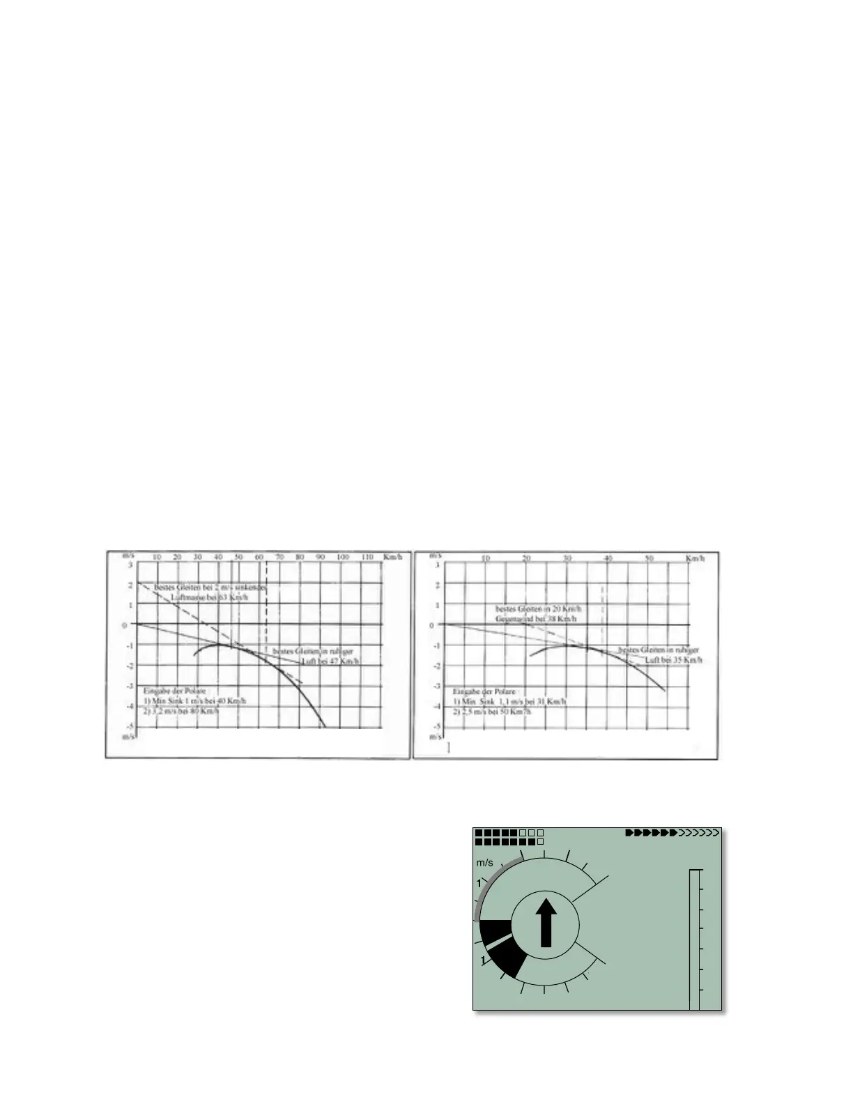
From the polar data entered in Menu>Pilot settings>Polar data the 6030 knows the glider sink rate for each
flight speed. If the current sink rate measured by the vario is more than the value found in this table, the glider is
in sinking air. If, for example, using the polar curves shown below, the vario displays a sink rate of 100 ft/min
(0.5 m/sec) when flying at 22 mph (35 km/h), the pilot must be in air rising at 160 ft/min (1.3 - 0.5 = 0.8 m/sec).
This is also shown by the netto vario (please also see Section 12.2, Netto Vario). Because the 6030 knows
the lift and sink rate of the surrounding air mass (if you have entered correct polar data for your glider and pilot
combination), it can continually plot new tangent lines to the polar curve to indicate the speed of the best glide in
any situation.
In the hang glider example (above left), the tangent line is drawn assuming a sink rate of the air mass of 2
m/sec (400 ft/min ). The best glide speed in this air mass is therefore 63 km/h (39 mph). The best glide speed is
the speed that allows the pilot to fly at the best glide ratio through the air.
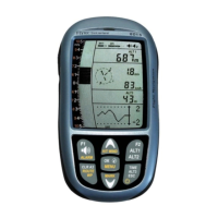
In the 6030 display for the hang gliding example (shown at
right), the pilot is flying too slowly. Note that the McCready
indictor is in the negative range of the dial. At this speed the
pilot dawdles in the sinking air, and will therefore waste both
altitude and time. Conversely, if the pilot flies faster than the
6030’s recommended speed of 63 km/h (39 mph), the pilot
would arrive lower than a pilot flying at the optimal speed of 39
mph.
In the paraglider polar curve above, the tangent line is drawn for
a head wind of 20 km/h (12 mph) and the resulting best glide is
38 km/h (24 mph). If the pilot flies with an activated GPS so that