COMPETITION ROUTE. Press the OK key and 6030 will return to the run mode with the optimized Competition
Route active. Once the optimized route option has been enabled it will stay active until it is disabled. This
means that if you copy a new route to the Competition Route the new route will be optimized. To disable route
optimization, long press the Route key, the lower half of the display will show the Opt. COMPETITION ROUTE
highlighted, press the F1 (Optim C RTE) key, Opt. COMPETITION ROUTE in the list will be changed to
COMPETITION ROUTE, press the OK key and 6030 will return to the run mode. The optimized route function
can be turned off/on in flight, if desired, as described above.
If the Route list is viewed from the Main Menu, when
the optimized route is selected but the route is not
active, the COMPETITION-ROUTE is shown as Opt.
COMPETITION-ROUTE and, if selected, the total
center-to-center distance of the route as well as
the optimized route distance is shown in the lower
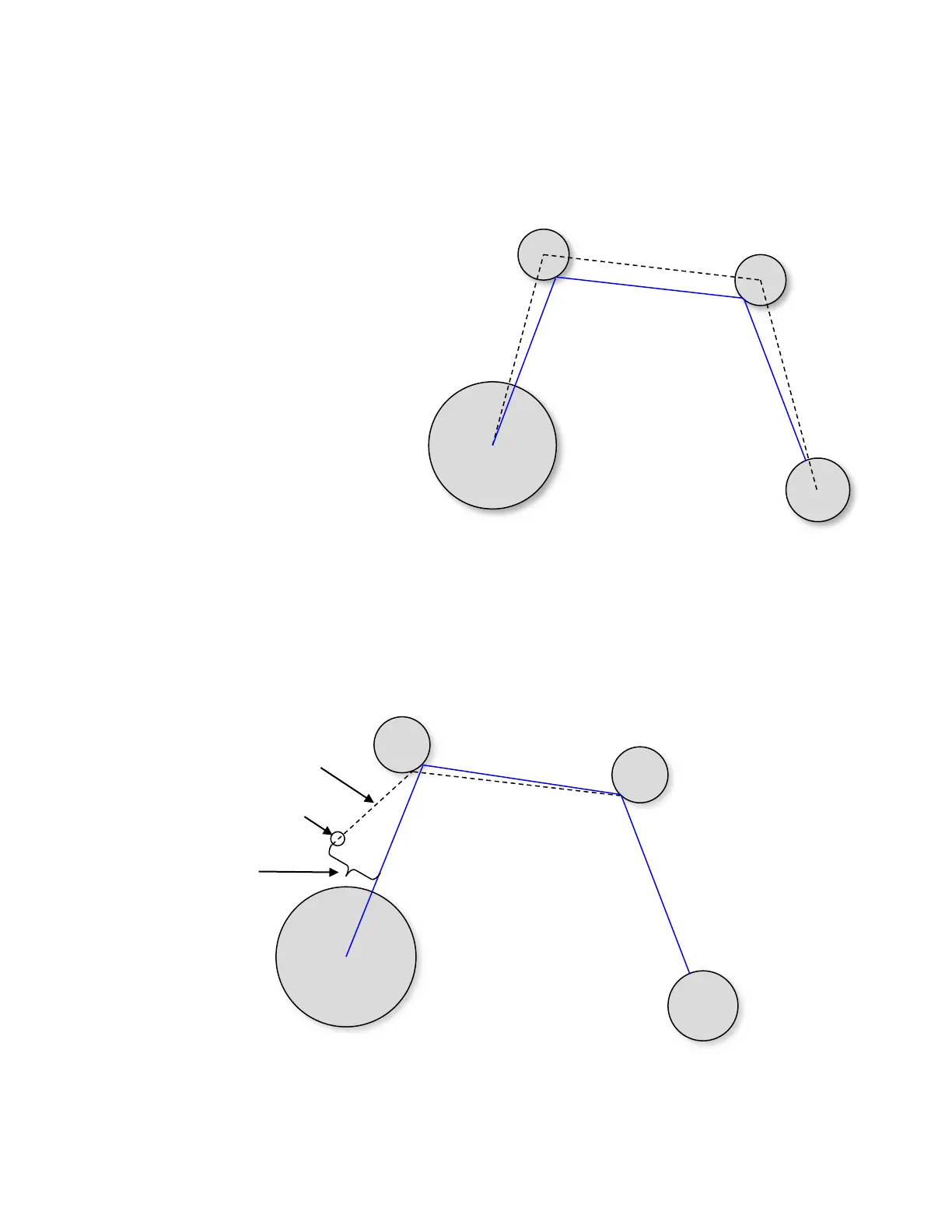
half of the display. The optimized and un-
optimized total distance is calculated as shown
in the example. C-Wp refers to the optimal
intercept calculated by the instrument. The
dashed black line represents the normal
Competition Route (distance =14km),
whereas, the solid blue line represents the
optimized route (distance <14km). When
an optimized Competition Route is active it
will be shown on the Map page and the
optimal intercepts (C-Wp) will be shown on the
turnpoint cylinders.
5.4.2.1 Flying an Optimized Competition Route
In flight, if your cross track error divided by the distance to the cylinder is greater than 0.2 (~11º) a new optimum
intercept is calculated and you will see the map update the current C-Wp and bearing line as shown in the
diagram. Of course, all of the related user-fields and compass pointers are updated as well. Note: the C-Wp for
subsequent turnpoints remains unchanged.