frequency of the McCready tone is proportional to the speed ring setting that you are flying (i.e., the higher the
speed ring setting that you fly, the higher the frequency of the McCready tone). If the tone lowers while you are
gliding, then you need to speed up and vice versa. With the McCready sounds on, you do not need to watch the
indicator continuously, but can react to vario changes by adjusting your speed to the changing McCready tone.
A dead band can be set so that there is no McCready sound when you are gliding within a certain range of the
desired speed ring setting. For more information about McCready sounds see Section 3.5.
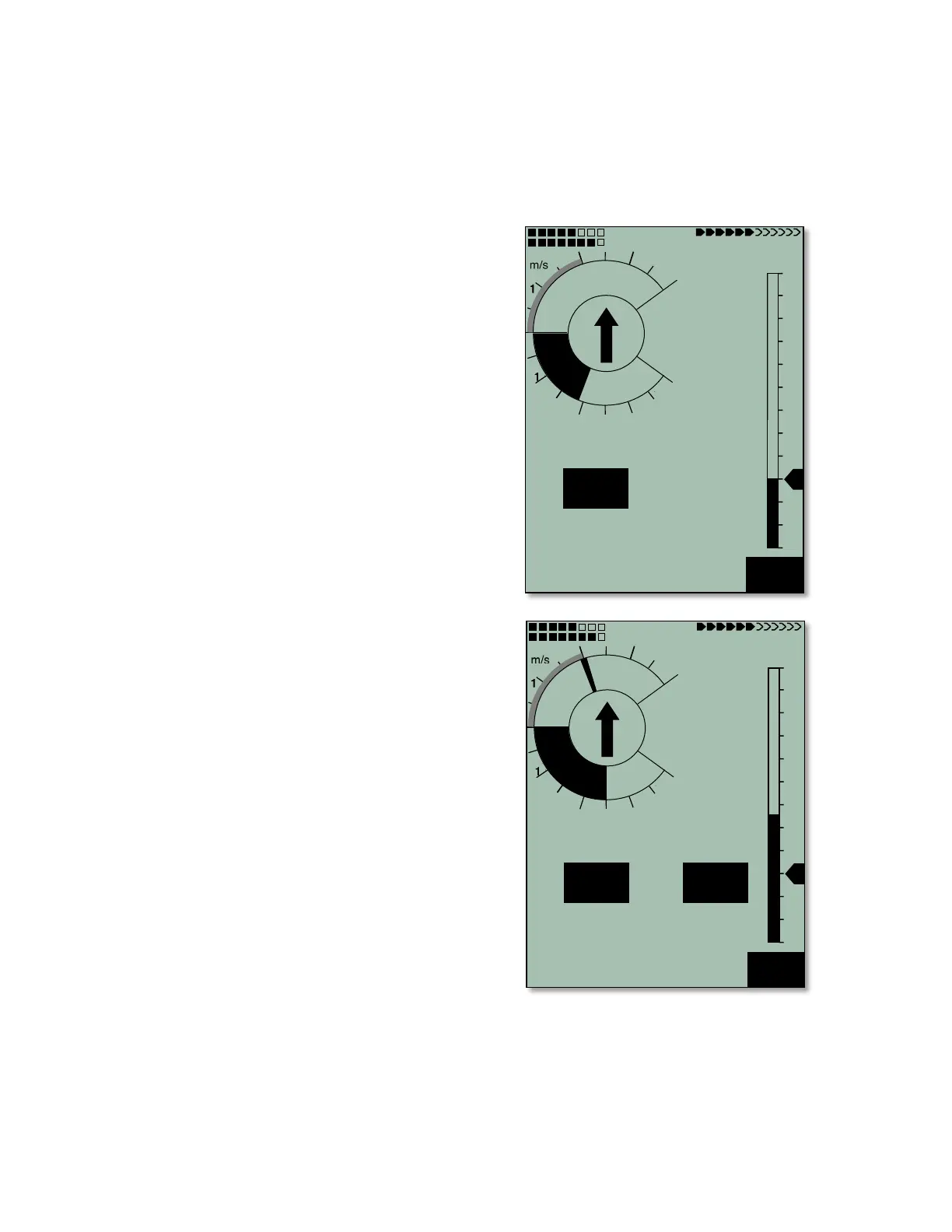
A possible scenario: A pilot is crossing a valley at a relatively
high speed. Due to more-than-anticipated sink encountered on
course line, there is a risk that the pilot may not be able to clear
the ridge on the other side of the valley. So that the least
amount of altitude is lost from this point forward, the pilot
should reduce speed until the McCready indicator is on zero
(i.e., best glide speed). With a speed ring setting of 0 the best
glide indicator on the right side of the analog speed scale will
correspond with the actual present speed (see top figure). In
this example, the pilot is flying at the best glide speed for this
air mass. The flight speed of 47 km/h corresponds to the best
glide indicator and the McCready indicator is on 0. The average
climb in the last thermal was 2.0 m/sec.
If the pilot were to further reduce speed, the McCready
indicator would run into the negative range of the dial. This
must be avoided, because in this case the pilot will waste
unnecessarily both time and altitude. The 6030 will sound a
rapid low beep tone if the pilot flies slower than best glide
speed. This will most likely happen when a pilot flies right at
best glide speed and then encounters sinking air. In that case
the pilot should speed up to remain at best glide speed.
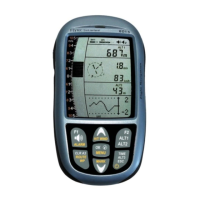
To fly at the McCready optimum speed, assuming that the
climb rate expected in the next thermal is equal to the Average
Thermal Climb indicator, the pilot should adjust air speed until
the McCready indicator points to the value to which the
Average Thermal Climb indicator has filled on the dial scale
(see figure bottom right). In this example the pilot is flying the
correct speed for an anticipated next climb of 2 m/sec,
corresponding to a flight speed of 62 km/h. Note that the
McCready indicator (radial line) points to 2 m/sec, which was
the average climb rate for the last thermal.
Of course, the next climb may be different than the previous
one, so the pilot may elect to fly with the McCready indicator
above or below the Average Thermal Climb indicator. A
conservative pilot might prefer to fly with the McCready
indicator between zero (best glide) and the value of the
Average Thermal Climb indicator.
All the functions described here can be sampled in Simulation
mode. The measured values such as speed, sink or climb,
flight direction and ground speed can be varied by the user.
Their effects can be observed on the display and the resulting
tones can be heard.