103
11-2. Expanded Matrix System Example
The following procedure explains how to set up an Expanded Matrix link using three MFR-3232
units.
<Setting Up the Main Unit Link>
1. Refer to Sec. 3-2-2 "Expanded Matrix System Example" in the MFR-1616/ 1616R/ 3216/
3216RPS/ 3232/ 3232RPS/ 1616A Operation Manual to change IP addresses for the Main
Units, for example, as shown in the table below, and ensure that IP addresses in the same
subnet do not conflict.
2. Connect all devices, the Main and Remote Control Units and a PC(GUI), within the system.
3. Access to the [Web-based Control] of the MFR-3232 to be set as the Master unit by specifying
its URL. (http://192.168.1.12 in the example above)
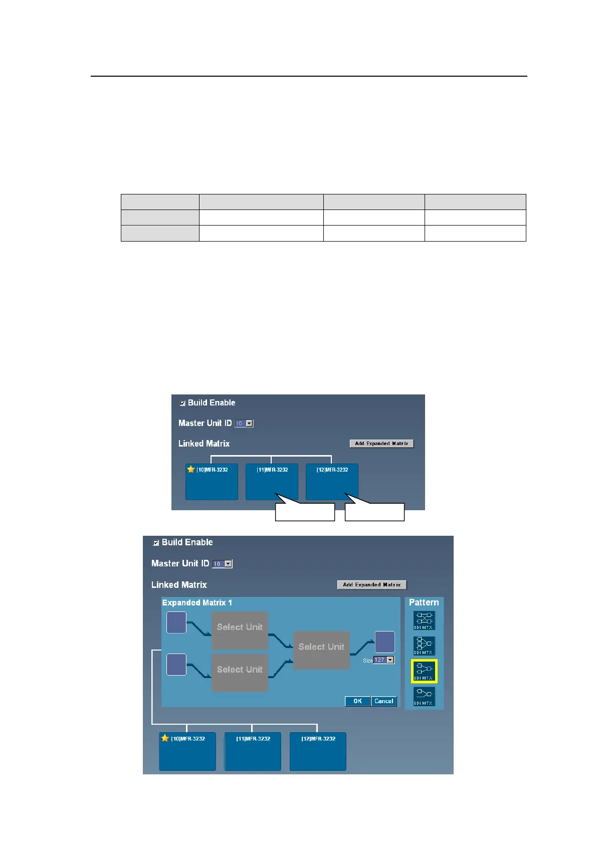
4. Open the Build Settings page and set link settings as shown below.
a. Check on the Build Enable check box.
b. Select 10 for the Master Unit ID.
c. Click Link on the MFR-3232 displayed in the Linked Matrix area, then click Send.
5. Re-open the Build Settings page of the Master unit. The starred MFR system becomes to
Main Unit (Master) and the two other MFR-3232 units appears on the navigation tree in the left
pane.
Click Link on the two units to make them Slave units.
6. Click Add Expanded Matrix to display the Matrix Setup area.
 Loading...