A Main Specifications
313
Appendix
A.5 Parallel Interface
This section describes the parallel interface (Centronics interface conforming to
the IEEE1284 standards) installed in this printer.
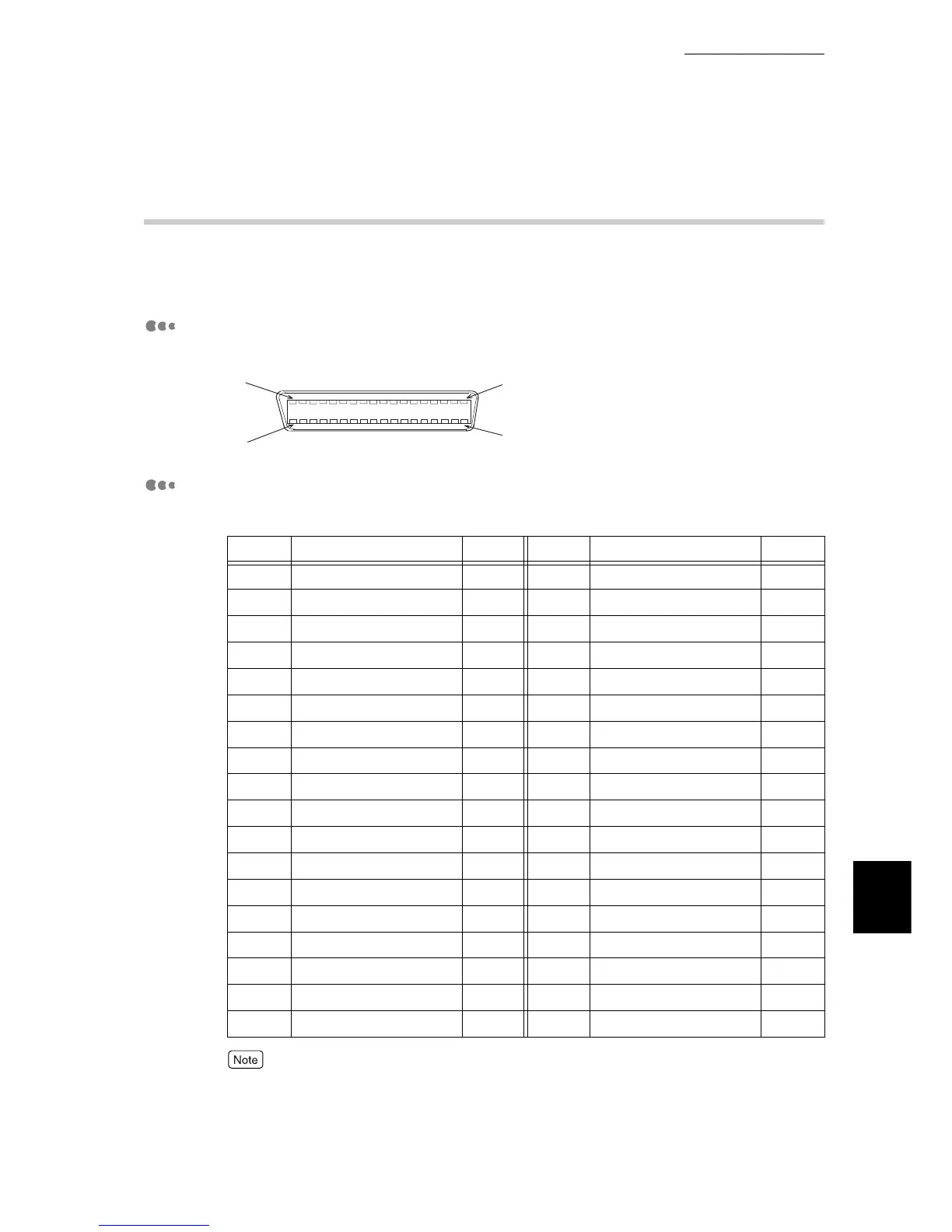
Connector Shape
The printer has an IEEE1284-B type connector. The connector shape is as follows:
Pin Arrangement
When both directions are OFF, the signal pin arrangement is as follows:
●
I/O indicates the direction from the viewpoint of the printer. field, I represents an input signal, O
represents an output signal, and Å| represents no signal.
●
When both directions are ON, the wiring conforms to the standard of IEEE1284-B type connector.
Pin No.
Signal Name I/O
Pin No.
Signal Name I/O
1 nStrobe I 19 Signal Ground -
2 Data1 I 20 Signal Ground -
3 Data2 I 21 Signal Ground -
4 Data3 I 22 Signal Ground -
5 Data4 I 23 Signal Ground -
6 Data5 I 24 Signal Ground -
7 Data6 I 25 Signal Ground -
8 Data7 I 26 Signal Ground -
9 Data8 I 27 Signal Ground -
10 nAck O 28 Signal Ground -
11 Busy O 29 Signal Ground -
12 PError O 30 Signal Ground -
13 Select O 31 nInit I
14 nAutoFd I 32 nFault O
15 (RESERVED) - 33 (RESERVED) -
16 Logic GND - 34 (RESERVED) -
17 Chassis Gnd - 35 (RESERVED) -
18 Peripheral Logic High O 36 nSelectIn I
 Loading...