Upgrade and Maintenance Manual BX900 S2
Contents
© cognitas. Gesellschft für Technik-Dokumentation mbH 2011 Pfad: C:\Programme\FCT\tim_app\tim_local\work\WALTER\OBJ_DOKU-13649-001.fm
11.2.2 Preliminary steps . . . . . . . . . . . . . . . . . . . . . . . . 160
11.2.3 Removing the front docking board . . . . . . . . . . . . . . . 161
11.2.4 Installing the front docking board . . . . . . . . . . . . . . . . 164
11.2.5 Concluding steps . . . . . . . . . . . . . . . . . . . . . . . . 166
12 Midplane . . . . . . . . . . . . . . . . . . . . . . . . . . . . 167
12.1 Basic information . . . . . . . . . . . . . . . . . . . . . . . 167
12.2 Replacing the midplane . . . . . . . . . . . . . . . . . . . . 169
12.2.1 Required tools . . . . . . . . . . . . . . . . . . . . . . . . . 169
12.2.2 Preliminary steps . . . . . . . . . . . . . . . . . . . . . . . . 169
12.2.3 Removing the rear chassis . . . . . . . . . . . . . . . . . . . 170
12.2.4 Removing the midplane . . . . . . . . . . . . . . . . . . . . . 172
12.2.5 Installing the midplane . . . . . . . . . . . . . . . . . . . . . 173
12.2.6 Installing the rear chassis . . . . . . . . . . . . . . . . . . . . 173
12.2.7 Concluding steps . . . . . . . . . . . . . . . . . . . . . . . . 173
13 Appendix . . . . . . . . . . . . . . . . . . . . . . . . . . . . 175
13.1 Mechanical overview . . . . . . . . . . . . . . . . . . . . . 175
13.1.1 System unit front . . . . . . . . . . . . . . . . . . . . . . . . 175
13.1.2 System unit rear . . . . . . . . . . . . . . . . . . . . . . . . 176
13.1.3 System unit interior . . . . . . . . . . . . . . . . . . . . . . . 177
13.2 Configuration tables . . . . . . . . . . . . . . . . . . . . . . 178
13.2.1 Server blade / storage blade fitting rules . . . . . . . . . . . . 178
13.2.2 Power supply unit / fan module fitting rules . . . . . . . . . . . 178
13.2.3 Connection blade fitting rules and port assignment . . . . . . . 179
13.3 Connectors and indicators . . . . . . . . . . . . . . . . . . 179
13.3.1 Front of system . . . . . . . . . . . . . . . . . . . . . . . . . 179
13.3.1.1 Control elements on the Local Service Display . . . . . . . 180
13.3.1.2 LEDs on the control panel . . . . . . . . . . . . . . . . . . 181
13.3.2 Back of system . . . . . . . . . . . . . . . . . . . . . . . . . 183
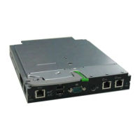
13.3.2.1 Connectors on the management blade . . . . . . . . . . . 183
13.3.2.2 Control elements and indicators on the management blade 184
13.3.2.3 Indicators on the hot-plug power supply units . . . . . . . . 186
13.3.2.4 Indicators on the fan modules . . . . . . . . . . . . . . . . 187
13.3.3 Indicators and connectors of the connection blades . . . . . . 188
13.3.3.1 Connection Blade GbE Switch/IBP 18/6 (SB6) . . . . . . . 188
13.3.3.2 Connection Blade GbE Switch/IBP 36/12 (SB11A) . . . . . 189
 Loading...