U41057-J19-Z146-1-76 July 2004 02–TX150S2–113
Removal/installation routines System board
© Siemens Nixdorf Informationssysteme AG 1995 Pfad: P:\02-systemeinheiten\TX150S2\TX150S2-e\TX150S2-e.k04
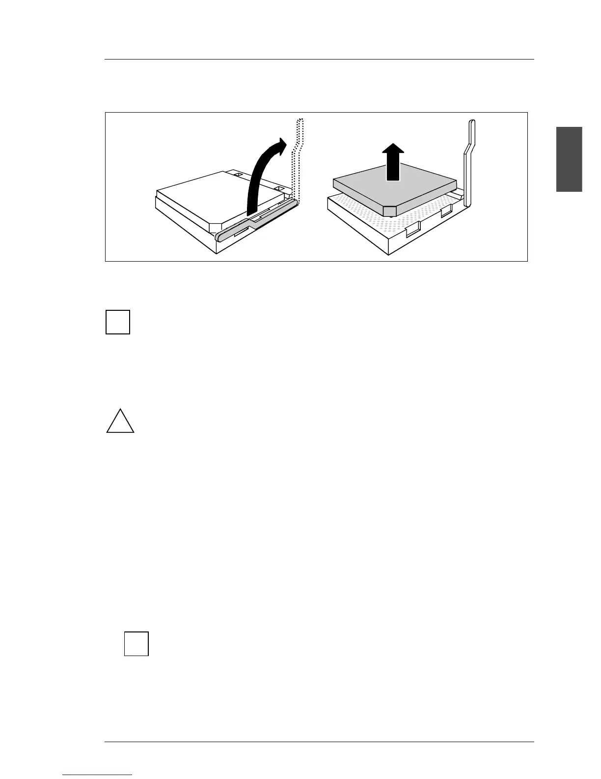
Installing/removing the processor module
Ê Release the socket lever by pressing it sideways and lifting it up to a 90°
angle (1).
There will be some resistance.
Ê Carefully lift the installed processor module out of the socket (2).
Ê Position the new processor above the socket, and insert it into the socket by
carefully pushing downwards.
The processor can only be installed in one direction in the socket. Pay
attention to the marking (triangled, golden colored) on one of the corners
for the correct alignment. To avoid damaging the pins and the processor,
do not force the processor into the socket.
Ê Lock the processor in the socket by pushing the socket lever back in place.
Ê Clean the surface of the processor.
Preparing the heat sink with the processor fan
Ê Remove any resting parts of the conductive paste from the underside of the
heat sink.
Ê Clean the underside of the heat sink with a solvent (e.g. Isopropyl alcohol)
or a rag.
On the market rags are available which are moistened with Isopropyl
alcohol, named CleanTex TexPad 801.
1
2
i
!
i
 Loading...